How to check the infrared receiver and its pinout. Diagram of an IR receiver for remote control of electrical appliances. Reading data only from those remotes that work according to the specified protocol
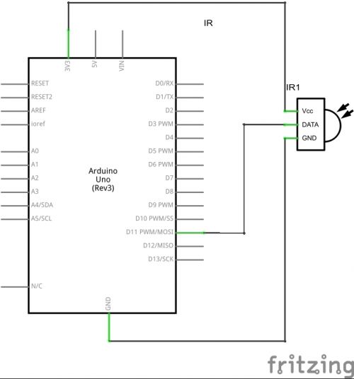
Today's article will look at connecting the TSOP34836 IR receiver to an Aduino UNO board. For these purposes, you can use any receiver you have that is compatible with your remote control in frequency. The pin assignment is shown in the figure.
1. Vout - receiver output.
2. GND - "ground", common wire.
3. Vcc - power.
Data transmission from the IR remote control to the receiver is carried out according to the RC5 protocol, which is a sequence of pulses. Connection is carried out according to the following scheme.
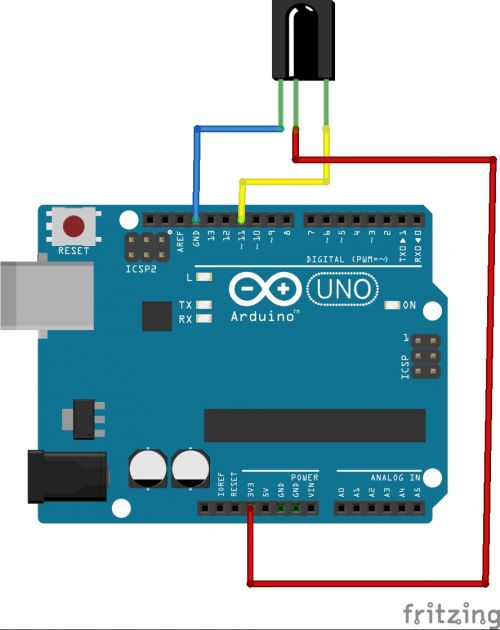
And having collected, we get something like this:
To process the data transmitted by the remote control, we use the IRremote library, this library is attached to the article. Paste the following code:
#include "IRremote.h" IRrecv irrecv(11); // Specify the pin to which the receiver is connected decode_results results; void setup() ( Serial.begin(9600); // Set COM port speed irrecv.enableIRIn(); // Start receiving ) void loop() ( if (irrecv.decode(&results)) // If data has arrived ( Serial .println(results.value, HEX); // Send the received data to the console irrecv.resume(); // Accept the following command ) )
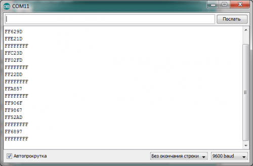
Now in the COM - port console you can see the code of the pressed key in HEX.
That's all, now you can use this scheme in your devices. Below is an example of one of the practical applications of an IR receiver.
As a demonstration, I will show you how to control the servo using the IR remote control.
Device Diagram:

This is how it should look like:

We use the following code to run the device:
#include "Servo.h" #include "IRremote.h" IRrecv irrecv(11); decode_results; Servo main; intservPoz = 90; //Initial position of the servo int lastPoz = 0; void setup() ( irrecv.enableIRIn(); servoMain.attach(10); // Servo attached to pin 10 servoMain.write(servPoz); ) void loop() ( if (irrecv.decode(&results)) ( int res = results.value; Serial.println(res, HEX); if(res==0xFFFF906F)// If "+" button is pressed ( lastPoz=res; servPoz++; servoMain.write(servPoz); ) else if(res== 0xFFFFA857)// If the "-" button is pressed ( servPoz--; lastPoz=res; servoMain.write(servPoz); ) else if(res==0xFFFFFFFF)// If the button is held down ( if(lastPoz==0xFFFF906F) servPoz++; // Hold "+" if(lastPoz==0xFFFFA857) servPoz--;// Hold "-" servoMain.write(servPoz); ) irrecv.resume(); delay(100); ) )
The remote control is used some kind of Chinese, when you press "+" the servo rotates in one direction, when you press "-", in the other.
scheme from the magazine "Young Technician".
An interesting direction of radio electronics, which supplemented this electronics with new advantages of "invisible" light (infrared light). So I propose a diagram of a simple (for example) receiver and transmitter based on infrared rays. Basis: operational amplifier k140ud7 (I have ud708 here), emitting and receiving IR photodiodes, ULF (k548un1a (b, c - indices) - for two channels) (although where the second channel of the amplifier "turn on" is up to you - the transmitter circuit is designed for one channel i.e. mono). Power supply of the device: in general I recommend it with decent stabilization of currents (and the "dendy" adapter is annoying with the background of the "network"). Method: the amplitude-modulated signal of the transmitter is amplified by the receiver by 1000 times.
How the device works. I suggest you watch a short video testing the IR remote control "by ear". You can quickly check the performance and signal strength by sound.
Diagram of IR receiver and IR transmitter
When assembling, capacitors C1 and C2 should be as close to the amplifier as possible! High-impedance headphones can be connected to the output (low-impedance headphones require a separate ULF). Photodiode FD7 (I have FD263: "pill" with a focusing lens); 0.125W resistors: R1 with R4 set the signal strength factor to 1000 times. The receiver is easy to set up: the photodiode is directed to a source of IR radiation, for example, a 220v-50Hz lamp: the filament will be emitted at a frequency of 50Hz or the remote control from the TV (video, etc.). The sensitivity of the receiver is high: it normally receives signals reflected from the walls .
The IR transmitter has AL107a LEDs: any will do. R2 2 kOhm, C1 1000mkFx25V, C2 200mkFx25V, any transformer is also. Although it is quite possible to do without a transformer - apply an amplified audio signal to capacitor C2.

Device diagram
Diagram of an IR receiver with ULF
Recently, out of necessity, I assembled an IR receiver to test IR remotes (TVs and DVDs). After finalizing the circuit, I installed a mono ULF TDA7056. This amplifier has good gain characteristics of about 42 dB; operates in the voltage range from 3V to 18V, which allowed the IR receiver to work even at a voltage of 3V; TDA gain range from 20 Hz to 20 kHz (UD708 skips up to 800 kHz) is quite enough to use the receiver as an audio accompaniment; has protection against short circuit on all "legs"; protection against "overheating"; weak self-interference coefficient. In general, I liked this compact and reliable ULF (we have it for 90 rubles).
There is a detailed description for it. Figure 1 shows an example of using an amplifier.

Photo TDA7056

Fig.1. Amplifier circuit with TDA7056
The result is an IR receiver (Fig. 2), which operates in the voltage range from 3V to 12V. I recommend using batteries to power the receiver, or batteries. When using a power supply, a stabilized source is required, otherwise a 50Hz network background will be heard, which amplifies the UD708. If the device is located near a source of mains voltage or radio radiation, interference may occur. To reduce interference in the circuit, it is necessary to include capacitor C5. TDA7056 is designed for a 16 ohm output speaker, unfortunately I don’t have one. I had to use a 4 ohm 3 watt speaker that was connected through a 1 watt 50 ohm resistor. Too low speaker coil resistance causes excess power and overheats the amplifier. In general, due to the additional resistor, the ULF does not heat up, but provides quite acceptable gain.
The IR receiver plays an important role in our everyday life. With the help of this microcircuit, we are able to control the modern benefits of household appliances, a TV, a music center, a car radio, and an air conditioner. This allows us to do, the remote control (RC), let's take a closer look at its operation, circuit, purpose and verification. In the article, how to check the IR receiver yourself.
What is an IR receiver and how does it work
This is an integrated circuit, its direct and main task is to receive and process an infrared signal, which just gives out the remote control. With the help of this signal, the equipment is controlled.
This microcircuit is based on a pin photodiode, a special element, with a p-n junction and an i region between them, an analogue of the base of a transistor, like in a sandwich, here you have the abbreviation pin, in its own way, a unique element.
It is switched on in the opposite direction and does not pass electric current. The IR signal enters the i area, and it conducts current, converting it into voltage.

The next steps, an integrating filter, an amplitude detector, and output transistors are waiting for them at the finish line.
As a rule, buying a new IR receiver in a store does not make much sense, since it can be freely removed from various electronic boards. If you are assembling a device for checking the remote control, from improvised materials, without knowing the exact marking of the device, then you can determine the pinout yourself.

We will need a multimeter, a power supply or several batteries, connecting wires, installation can be done hinged.
It has three outputs, one is GND, plus 5 volts is supplied to the second, and the out signal comes out from the third. We connect the power, respectively, to the first and second legs, and remove the voltage from the third.

It is in a state of waiting for a signal from the remote control, and on the multimeter we see five volts. We begin to switch channels or press other buttons by pointing the remote control at it.
If it is working, then the voltage will sag, by about 0.5-1 volts. If everything happens as it is written here, the device is working, otherwise, the element is not working.
How to determine the pinout of an infrared receiver
For example, I took a chip that was completely unknown to me, which lay in a box with elements, “minus”, was determined, by the point that is on the reverse side of the element, “plus”, empirically through a resistor. I didn’t risk anything, there was no hope that he was originally a worker.
To determine the pinout of the IR receiver, if it is soldered to the board, look at it, perhaps there is a pin marking. If nothing is written there, inspect the element itself, look for its name, and then look on the Internet for characteristics and data, such business is very competent. Following the instructions, how to check the IR receiver yourself.
An IR remote control receiver for controlling household appliances can be easily made using the CD4017 decimal counter, NE555 timer and TSOP1738 infrared receiver.
Using this IR receiver circuit, you can easily control your household appliances using the TV remote control, DVD player, or using the remote control circuit described at the end of the article.
IR receiver circuit for remote control
Pins 1 and 2 of the TSOP1738 IR receiver are used to power it. Resistor R1 and capacitor C1 are designed for stable operation and suppression of various interferences in the power circuit.

When IR beams at 38kHz hit the TSOP1738 IR receiver, its output 3 goes low, and when the IR beams disappear, it goes high again. This negative pulse is amplified by transistor Q1, which sends an amplified frequency signal to the input of the CD4017 decimal counter. Counter outputs 16 and 8 are designed to power it. Pin 13 is connected to ground, allowing it to work.
The output of Q2 (pin 4) is connected to the reset pin (pin 15) to make the CD4017 work as a bistable multivibrator. During the first pulse, Q0 goes log 1, the second clock signal causes Q1 to go log 1 (Q0 goes low), and the third clock causes Q0 to log 1 again (Q2 is connected to MR, so the third clock signal resets the counter).
Let's assume the counter has reset (Q0 is high and the rest are low). When you press the remote control button, the clock signal affects the counter, which leads to a high level on Q1. Thus, LED D1 lights up, transistor Q2 turns on and the relay is activated.
When the remote control button is pressed again, a log 1 appears at the Q0 output, the relay turns off and LED D2 lights up. LED D1 indicates when the fixture is on and LED D2 indicates when the fixture is off.
You can use your TV remote control to control it, or you can assemble a separate one according to the diagram below.
The IR receiver is a standard device connected to the COM (RS-232) port and used for remote control of the robot.
One of the possible schemes of the IR receiver. For the IR receiver, any 5-volt infrared receiver used in consumer equipment (TVs) will do. For example: TSOP1836, IS1U60L, GP1U52X, SFH506-36 or our domestic TK1833. The voltage stabilizer KREN5A is required to power the IR receiver with 5 volts, because 12 volts is supplied from the 7th pin of the COM port. The resistor can be selected from the range of 3-5 kOhm, the capacitor is 4.7-10 uF. Any low power diode.
In the above diagram, the output signal is applied to 1 pin of the COM port (DCD). This pin is not used by a standard mouse for a COM port, so if you do not have enough free COM port, this circuit can be used in parallel with a mouse (but not with a modem)! The output signal can be applied not only to DCD, but also to other pins, such as CTS or DSR. All these parameters can be set in the program that works with the IR receiver. There are several variants of the program, the most common program is WinLIRC. I can also advise you to use the Girder program.
Pinout and appearance of the main elements of the circuit

From left to right - two types of 5-volt IR receivers, and a voltage regulator chip KREN5A.
COM port pinout
Pinout and description of the contacts of the COM port (25 pin).
The IR receiver plays an important role in our everyday life. With the help of this microcircuit, we are able to control the modern benefits of household appliances, a TV, a music center, a car radio, and an air conditioner. This allows us to do, the remote control (RC), let's take a closer look at its operation, circuit, purpose and verification. In the article, how to check the IR receiver yourself.
What is an IR receiver and how does it work
This is an integrated circuit, its direct and main task is to receive and process an infrared signal, which just gives out the remote control. With the help of this signal, the equipment is controlled.
This microcircuit is based on a pin photodiode, a special element, with a p-n junction and an i region between them, an analogue of the base of a transistor, like in a sandwich, here you have the abbreviation pin, in its own way, a unique element.
It is switched on in the opposite direction and does not pass electric current. The IR signal enters the i area, and it conducts current, converting it into voltage.

The next steps, an integrating filter, an amplitude detector, and output transistors are waiting for them at the finish line.
As a rule, buying a new IR receiver in a store does not make much sense, since it can be freely removed from various electronic boards. If you are assembling a device for checking the remote control, from improvised materials, without knowing the exact marking of the device, then you can determine the pinout yourself.

We will need a multimeter, a power supply or several batteries, connecting wires, installation can be done hinged.
It has three outputs, one is GND, plus 5 volts is supplied to the second, and the out signal comes out from the third. We connect the power, respectively, to the first and second legs, and remove the voltage from the third.

It is in a state of waiting for a signal from the remote control, and on the multimeter we see five volts. We begin to switch channels or press other buttons by pointing the remote control at it.
If it is working, then the voltage will sag, by about 0.5-1 volts. If everything happens as it is written here, the device is working, otherwise, the element is not working.
How to determine the pinout of an infrared receiver
For example, I took a chip that was completely unknown to me, which lay in a box with elements, “minus”, was determined, by the point that is on the reverse side of the element, “plus”, empirically through a resistor. I didn’t risk anything, there was no hope that he was originally a worker.
To determine the pinout of the IR receiver, if it is soldered to the board, look at it, perhaps there is a pin marking. If nothing is written there, inspect the element itself, look for its name, and then look on the Internet for characteristics and data, such business is very competent. Following the instructions, how to check the IR receiver yourself.
scheme from the magazine "Young Technician".
An interesting direction of radio electronics, which supplemented this electronics with new advantages of "invisible" light (infrared light). So I propose a diagram of a simple (for example) receiver and transmitter based on infrared rays. Basis: operational amplifier k140ud7 (I have ud708 here), emitting and receiving IR photodiodes, ULF (k548un1a (b, c - indices) - for two channels) (although where the second channel of the amplifier "turn on" is up to you - the transmitter circuit is designed for one channel i.e. mono). Power supply of the device: in general I recommend it with decent stabilization of currents (and the "dendy" adapter is annoying with the background of the "network"). Method: the amplitude-modulated signal of the transmitter is amplified by the receiver by 1000 times.
How the device works. I suggest you watch a short video testing the IR remote control "by ear". You can quickly check the performance and signal strength by sound.
Diagram of IR receiver and IR transmitter
When assembling, capacitors C1 and C2 should be as close to the amplifier as possible! High-impedance headphones can be connected to the output (low-impedance headphones require a separate ULF). Photodiode FD7 (I have FD5 .. some kind of "tablet" with a focusing lens - I don't remember the exact name); 0.125W resistors: R1 with R4 set the signal strength factor to 1000 times. The receiver is easy to set up: the photodiode is directed to a source of IR radiation, for example, a 220v-50Hz lamp: the filament will be emitted at a frequency of 50Hz or the remote control from the TV (video, etc.). The sensitivity of the receiver is high: it normally receives signals reflected from the walls .
The IR transmitter has AL107a LEDs: any will do. R2 2 kOhm, C1 1000mkFx25V, C2 200mkFx25V, any transformer is also. Although it is quite possible to do without a transformer - apply an amplified audio signal to capacitor C2.

Device diagram
Recently, out of necessity, I assembled an IR receiver to test IR remotes (TVs and DVDs). After finalizing the circuit, I installed a mono ULF TDA7056. This amplifier has good gain characteristics of about 42 dB; operates in the voltage range from 3V to 18V, which allowed the IR receiver to work even at a voltage of 3V; TDA gain range from 20 Hz to 20 kHz (UD708 skips up to 800 kHz) is quite enough to use the receiver as an audio accompaniment; has protection against short circuit on all "legs"; protection against "overheating"; weak self-interference coefficient. In general, I liked this compact and reliable ULF (we have it for 90 rubles).
There are to him with. Figure 1 shows an example of using an amplifier.

Photo TDA7056

Fig.1. Amplifier circuit with TDA7056
The result is an IR receiver (Fig. 2), which operates in the voltage range from 3V to 12V. I recommend using batteries to power the receiver, or batteries. When using a power supply, a stabilized source is required, otherwise a 50Hz network background will be heard, which amplifies the UD708. If the device is located near a source of mains voltage or radio radiation, interference may occur. To reduce interference in the circuit, it is necessary to include capacitor C5. TDA7056 is designed for a 16 ohm output speaker, unfortunately I don’t have one. I had to use a 4 ohm 3 watt speaker that was connected through a 1 watt 50 ohm resistor. Too low speaker coil resistance causes excess power and overheats the amplifier. In general, due to the additional resistor, the ULF does not heat up, but provides quite acceptable gain.

Fig.2. Diagram of an IR receiver with ULF

Photo of IR receiver
In this lesson, we will consider connecting an IR receiver to Arduino. We will tell you which library should be used for the IR receiver, demonstrate a sketch for testing the operation of an infrared receiver from a remote control, and analyze the commands in the C ++ language to receive a control signal.
IR receiver device. Principle of operation
Infrared receivers are widely used in electronic technology due to their affordable price, simplicity and ease of use. These devices allow you to control devices using a remote control and can be found in almost any kind of technology.
How an IR receiver works. Remote control signal processing
The IR receiver on the Arduino is capable of receiving and processing an infrared signal in the form of pulses of a given duration and frequency. Typically, an IR receiver has three legs and consists of the following elements: a PIN photodiode, an amplifier, a bandpass filter, an amplitude detector, an integrating filter, and an output transistor.
Under the action of infrared radiation in the photodiode, which has between p And n regions created an additional region from the semiconductor ( i-area), the current begins to flow. The signal is fed to an amplifier and then to a bandpass filter that protects the receiver from interference. Interference can create any household appliances.
The bandpass filter is set to a fixed frequency: 30; 33; 36; 38; 40 and 56 kilohertz. In order for the signal from the remote control to be received by the Arduino IR receiver, the remote control must be at the same frequency as the filter in the IR receiver is set to. After the filter, the signal goes to the amplitude detector, the integrating filter and the output transistor.
How to connect an IR receiver to Arduino
Housings of infrared receivers contain an optical filter to protect the device from external electromagnetic fields, they are made in a special shape to focus the received radiation on the photodiode. To connect the IR receiver to the Arduino UNO, three legs are used, which are connected to the ports - GND, 5V and A0.
For the lesson we need the following details:
- Arduino Uno board;
- Bread board;
- USB cable;
- IR receiver;
- Remote control;
- 1 LED;
- 1 resistor 220 Ohm;
- Wires "folder-folder" and "folder-mother".
 Scheme of connecting the IR receiver to the Arduino analog port
Connect the IR receiver according to the diagram and the LEDs to pins 12 and 13 and upload the sketch.
#include // connect the library for the IR receiver IRrecv irrecv(A0); // specify the pin to which the IR receiver is connected decode_results; void setup() // procedure setup( irrecv.enableIRIn(); // start receiving infrared signal pinMode(13, OUTPUT); // pin 13 will be the output pinMode(12, OUTPUT); // pin 12 will be the output pinMode(A0, INPUT); // pin A0 will be an input (English "intput") Serial.begin(9600); // connect port monitor) void loop () // procedure loop ( if (irrecv.decode (&results)) // if the data came, execute the commands( Serial .println(results.value); // send the received data to the port // turn on and off the LEDs, depending on the received signal if (results.value == 16754775) ( digitalWrite (13, HIGH); ) if (results.value == 16769055) ( digitalWrite (13, LOW); ) if (results.value == 16718055) ( digitalWrite (12, HIGH); ) if (results.value == 16724175) ( digitalWrite(12, LOW); ) irrecv.resume(); // receive the next signal on the IR receiver } }
Explanations for the code:
- The IRremote.h library contains a set of commands and allows you to simplify the sketch;
- The decode_results statement assigns the received signals from the remote control to the variable name results .
What to look for:
- In order to be able to control the turning on of the LED, it is necessary to turn on the port monitor and find out what signal is sent by this or that button on the remote control;
- The received data should be entered into the sketch. Change the eight-character code in the sketch after the double equal sign if (results.value == 16769055) to your own.
IR receiver device, operation and verification
In television, household, medical equipment and other equipment, IR receivers of infrared radiation are widely used. They can be seen in almost any kind of electronic equipment, they are controlled using a remote control.
operation and block diagram of the IR receiver |

Typically, an IR receiver microassembly has three pins. One is common and is connected to the power minus GND, the other to the plus Vs, and the third is the output of the received signal Out.

Unlike a standard IR photodiode, an IR receiver is capable of not only receiving, but also processing an infrared signal in the form of pulses of a fixed frequency and a given duration. This protects the device from false alarms, background radiation and interference from other household appliances emitting in the IR range. Sufficiently strong interference for the receiver can be created by fluorescent energy-saving lamps with an electronic ballast circuit.
A micro-assembly of a typical IR radiation receiver includes: PIN photodiode, adjustable amplifier, band pass filter, amplitude detector, integrating filter, threshold device, output transistor

A PIN photodiode from the family of photodiodes, in which another region is created from its own semiconductor (i-region) between the n and p regions - this is essentially a layer of pure semiconductor without impurities. It is this that gives the PIN diode its special properties. In the normal state, no current flows through the PIN photodiode, since it is connected to the circuit in the opposite direction. When electron-hole pairs are generated in the i-region under the action of external IR radiation, a current begins to flow through the diode. Which then goes to an adjustable amplifier.
Then the signal from the amplifier goes to a bandpass filter that protects against interference in the IR range. The bandpass filter is tuned to a strictly fixed frequency. Typically, filters are applied that are tuned to a frequency of 30; 33; 36; 36.7; 38; 40; 56 and 455 kilohertz. In order for the signal emitted by the remote control to be received by the IR receiver, it must be modulated with the same frequency as the filter is set to.
After the filter, the signal goes to the amplitude detector and the integrating filter. The latter is necessary to block short single signal bursts that may appear from interference. Further, the signal goes to the threshold device and the output transistor. For stable operation, the gain of the amplifier is adjusted by the automatic gain control (AGC) system.

Housings of IR modules are made in a special shape to help focus the received radiation on the sensitive surface of the photocell. The body material transmits radiation with a strictly defined wavelength from 830 to 1100 nm. Thus, the device uses an optical filter. To protect the internal elements from the effects of external email. fields, an electrostatic shield is used.
Checking the IR Receiver |
Since the IR signal receiver is a specialized microassembly, in order to make sure that it works, you need to apply a supply voltage to the microcircuit, usually 5 volts. The current consumption in this case will be about 0.4 - 1.5 mA.
If the receiver does not receive a signal, then in the pauses between bursts of pulses, the voltage at its output practically corresponds to the supply voltage. Its between GND and the signal output pin can be measured with any digital multimeter. It is also recommended to measure the current consumed by the microcircuit. If it exceeds the standard one (see the reference book), then most likely the microcircuit is defective.
So, before starting the module test, we must determine the pinout of its outputs. This information is usually easy to find in our mega electronics datasheet guide. You can download it by clicking on the picture on the right.
Let's check on the TSOP31236 chip, its pinout corresponds to the figure above. We connect the positive output from the self-made power supply to the positive output of the IR module (Vs), and the negative output to the GND output. And we connect the third output OUT to the positive probe of the multimeter. We connect the negative probe to the common GND wire. We switch the multimeter to DC voltage mode at 20 V.

As soon as packets of infrared pulses begin to arrive at the photodiode of the IR microassembly, the voltage at its output will drop by several hundred millivolts. In this case, it will be clearly visible how the value on the multimeter screen decreases from 5.03 volts to 4.57. If we release the remote control button, then the screen will again display 5 volts.
As you can see, the IR receiver responds correctly to the signal from the remote control. So the module is correct. Similarly, you can check any modules in the integrated design.