How to separate the grounds and connect the housing when building a low-frequency amplifier? Connecting a two-channel and four-channel amplifier
For cars they are sometimes called subwoofer monoblocks. They are designed specifically for connecting multiple subwoofers.
Monoblocks have some distinctive features related to their scope of application and are widely popular.
Features of single-channel amplifiers
Many motorists want to purchase a candy bar because it has the following features and advantages.
- Firstly, these are mono amplifiers. When you feed them a stereo/mono signal from the radio, which is collected in the amplifier, you get a mono signal at the output through the subwoofer.
- Secondly, single-channel amplifiers have quite high power. At 4 ohms load the power per channel is from
- Thirdly, such subwoofer amplifiers must have a high-pass filter that cuts off all frequencies that are higher than the frequency of the filter settings. And this is a prerequisite for connecting a subwoofer.
- Fourthly, monoblocks often have a so-called subsonic filter, which cuts off ultra-low frequencies from the musical signal. This is quite an important thing, since contact with ultra-low frequencies on the subwoofer can cause it to break.
Famous manufacturers
Alpine is well known in many countries. The amplifier models it produces are distinguished by their compact size and high-quality sound. Digital broadband all-in-one PCs from Alpine are in constant high demand.
The Audison brand presents monoblocks for Hi-End cars, which are distinguished by detailed sound reproduction and high power. The manufacturer attaches a certificate of conformity to the device, which confirms the characteristics of all specified parameters.
Monoblocks from the Korean company Kicx are represented by many models with different capabilities, prices and functionality. This brand is a leader in the production of car amplifiers, speakers, subwoofers, cable products and components.

Choosing a monoblock
Single-channel power amplifiers have many parameters and characteristics that must be taken into account when choosing. The most important of them are:
- amplifier class;
- subwoofer power;
- minimum system resistance.
Most monoblocks on the market are class D. They have higher power and are smaller in size compared to A/B devices, and they heat up significantly less. But at the same time, the sound from single-channel class D amplifiers is slightly inferior in sound quality to A/B analogues. Although if the signal is sent to a subwoofer, you won’t notice the difference in quality.
Prices for class A/B monoblocks are lower, which is why they are a budget option.

Kicx AD 1.400
With the highest efficiency, the all-digital circuitry of this monoblock allows you to get up to 360 W of power for a four-channel amplifier and 650 W for a subwoofer model from miniature amplifiers. This single-channel amplifier for the Kicks subwoofer is from a series of economical, wide-range and ultra-compact Class D devices.
Specifications:
- amplifier class - D;
- dimensions - 170 x 46 x 323 mm;
- reproduced frequency range - 15 Hz-130 Hz;
- signal-to-noise ratio - >100 dB;
- sabsonic - 10-50 Hz/12 dB;
- LEDs - red fault indicator.
Alpine PDR-M65
The new PDR Series single-channel amplifiers feature a completely new design that delivers superior sound quality, high performance and excellent reliability. This digital mono amplifier has dual internal error correction technology. Now the input signal is first analyzed, then compared and corrected twice.
This monoblock uses a separate circuit for multi-stage power management. It constantly monitors critical component temperatures throughout the amplifier and reduces output power if necessary.

This amplifier has a stunningly clear and uncolored sound.
- Maximum power - 1300 W.
- Rated power - 450 W.
- Frequency range - from 8 to 400 Hz.
- Amplifier class - D;
- Dimensions - 229 x 165 x 51 cm.
Top seller
The Pioneer GM-D8601 single-channel car amplifier with remote control does not take up much space in the car. This Class D amplifier combines low 1 ohm output impedance with stable circuitry, surprisingly good output power, and installation flexibility.
- Rated power (4 Ohm) - 300 W.
- Channel power - 300 W.
- Frequency range: 10-240 Hz.
- Dimensions: 265 x 200 x 60 mm.
- Maximum power - 1600 W.
Audison AP 1D Prima
An extremely compact single-channel amplifier that is primarily designed for use with models equipped with the Prima series audio processor.

The monoblock has high power despite its miniature size. The amplifier's synchronization functions are configured entirely by the built-in 9-channel processor.
All amplifiers in this series, regardless of the number of channels, have the same dimensions and can be installed in a single vertical array on top of each other.
- Dimensions: 198 x 134 x 46 mm.
- Maximum power - 540 W.
- Channel 1 power (4 Ohms) - 310 W.
- Manufacturer: Italy.
Prologue
Often, during the first test of a homemade ULF, it turns out that it is phoning (amplifying an interference signal with a frequency of 50 or 100 Hertz) or reproducing some other unnecessary sounds. All these artifacts are especially clearly visible in the absence of a useful signal at the input.
The cause of interference can be either ULF excitation at ultrasonic frequencies, or the penetration of supply voltage ripples into the useful signal, or interference caused by external electromagnetic fields.
Excitation of the amplifier usually occurs due to a malfunction of the Negative Feedback (NFB) for direct current, for example, loss of capacitance of the NFC filter, or incorrect calculation of the VLF frequency response correction circuits. Excitation is easy to identify by the current consumption of the ULF and the distortion of the useful signal. In most cases, it is possible to disrupt the excitation of the ULF without any significant modifications to the design.
But it can be much more difficult to eliminate various kinds of interference associated with power supply or external interference that penetrates the amplification path due to design flaws.
Therefore, it is advisable, even during the design of the amplifier, to know about possible “clamps” and methods for eliminating them.
Let's look at the main reasons that cause hum and other interference in a speaker system and try to understand them using simplified equivalent circuits.

We will consider the symbol position 1 to be a connection to a common bus or, more simply, to a wire to which the common power wire and the common wire of the useful ULF signal are connected. In most low-frequency amplifiers, these two conductors are galvanically connected.
Conditional image of poses. 2 we designate the point of connection of the shielding elements with each other or with the ULF housing, if it is metal.
How to properly connect the input signal and power grounds?
Even at the ULF design stage, all circuits should be analyzed for the flow of currents from different sources through the same wires, screens or printed circuit board tracks. The most convenient way to do this is with the help of so-called equivalent circuits. It is not necessary to draw this diagram; it is quite enough to keep it in mind during design.

In this picture you see a diagram of connecting two independent alternating current generators to the corresponding loads. These two circuits have complete galvanic isolation and penetration of the signal from one generator into the load of the other is possible only through electromagnetic waves. But this is a shielding issue and we will look at it in the next paragraph.

This diagram shows the connection of two AC sources to loads using a common bus. The need to use a common bus arises due to the fact that the input circuits of the amplifiers and their power supply circuits are galvanically connected.
In addition, common buses can be used to save wire or to simplify the layout of printed circuit boards. Although, in some cases, for example, when designing printed circuit boards for pulsed or RF devices, there are other reasons.

Let's assume that only generator G1 is running and is generating some current into load R1. This current, flowing through a common bus that has some, even insignificant, resistance, which we will conventionally designate R3, will create a voltage drop on this very bus. This voltage will be applied through the internal resistance of the generator G2 to the load R2 and some interference current will flow through the latter. Thus, interference from generator G1 can enter load R2.
What does this threaten us with?
The noise voltage at the linear input of the amplifier can be fractions of a microvolt, while the magnitude of the ripple in the circuits of an unstabilized power supply can reach tenths of a volt. If we keep in mind that the input impedance of the ULF linear input is tens of kilo-ohms, then it becomes clear how these ripples can penetrate into the input circuits of the amplifier if the common buses are routed without regard to such an equivalent circuit.

Suppose we are assembling a signal amplifier according to the given circuit.

If we connect the connecting wires as shown in the diagram above, we will get a picture like this. As you can see, with this connection, a section has appeared on the common bus through which not only the input signal current will flow, but also the current from the power source.

To correct this mess, we move the connection point of the common wires of the power supply and the input signal, position 1, as close as possible to the amplifier circuit in order to reduce the influence of interference. Of course, these same principles will have to be followed when designing a printed circuit board.
How to organize shielding correctly?
Even if all the conductors of the amplifier's common bus are routed correctly, it is still not protected from the effects of interference that can be induced on the amplifier elements by external or internal electromagnetic fields.

The picture shows a familiar diagram of connecting two alternating current generators. But, in this case, we will try to trace how an external or internal electromagnetic field can cause interference to penetrate into the input circuits of the amplifier.
Let us conventionally designate the capacitance between the “hot” conductors of the generators as C1.

To minimize interference penetration, shielding is used.
This could significantly reduce the influence of external fields on the input signal if we did not run the G1 generator current through the cable shielding in the same way as was the case with the common bus described above.

Therefore, we will modify our circuit so as to prevent the flow of generator G1 current through the shielding braid. To do this, it is enough to connect the cable braid to the common bus at only one point.

Now we will use shielding of the signal wire in the ULF to protect it from interference.
When the level of the amplified signal is very low, the effects of interference from all kinds of electromagnetic radiation become noticeable. Electromagnetic waves easily penetrate the shielding braid of the wire, which is usually made of non-magnetic materials.
In order to minimize the level of interference in highly sensitive amplifier circuits, shielded twisted pair cable is used, which is popularly called a microphone cable.
The currents generated by electromagnetic fields in twisted pair wires flow in one direction and are almost equal, due to the identical shape of each twisted pair conductor. At the same time, the useful signal currents flow in different directions along the twisted pair conductors. Thus, in one wire the interference current is added to the useful signal, and in the other it is subtracted, which leads to complete compensation of the interference.
But, in amateur practice, twisted pair may not be needed so often, and is used only to connect a dynamic microphone or electromagnetic pickup to a pre-amplifier.

Typically, the linear input of a low-frequency amplifier is connected approximately according to this diagram. As you can see, the common line input wire is not connected to the socket body. At the same time, the socket body is connected to the metal body of the amplifier. In the same way, other shielding elements are connected to the metal amplifier housing, for example, the interwinding shield of the power transformer and the metal shield of the pre-amplifier.
But, in all cases, the common bus of the amplifier is connected to the metal case (screen) only at one point, position 1. If there are more than one such points, then the currents “traveling” through the metal body of the amplifier will begin to “look” into the common bus, which can cause interference.

If a 3.5mm jack type socket is used for the linear input, and the amplifier case is metal, then you will have to isolate the socket mount from the case, since the common terminal pos. 1 and the fastening elements pos. 2 in such sockets are galvanically connected.
So, let's summarize.
The metal housing of the amplifier must be connected to the common bus of the amplifier at only one point. Although other shielding elements, with the exception of those through which the useful signal flows, can be connected to the housing arbitrarily.
To connect weak signal sources, such as a dynamic microphone head or an electromagnetic pickup, use shielded twisted pair cable.
Evgenia Smirnova
To send light into the depths of the human heart - this is the purpose of the artist
Content
Connecting speakers to a laptop, TV, or other music source sometimes requires amplification of the signal using a separate device. The idea of building your own amplifier is a good one if you are inclined to work with printed circuit boards at home and have some technical skills.
How to make a sound amplifier
The beginning of work on assembling an amplification device for speakers of one type or another consists of searching for tools and components. The amplifier circuit is assembled on a printed circuit board using a soldering iron on a heat-resistant support. It is recommended to use special soldering stations. If you assemble it yourself for the purpose of testing the circuit or for use for a short period of time, the “on wires” option is suitable, but you will need more space to place the components. The printed circuit board guarantees the compactness of the device and ease of further use.
A cheap and widespread amplifier for headphones or small speakers is created on the basis of a microcircuit - a miniature control unit with a pre-wired set of commands for controlling an electrical signal. All that remains to be added to the circuit with the microcircuit is a few resistors and capacitors. The total cost of an amateur-grade amplifier is ultimately significantly lower than the price of ready-made professional equipment from the nearest store, but the functionality is limited to changing the output volume of the audio signal.

Remember the features of compact single-channel amplifiers that you assemble yourself based on TDA series microcircuits and their analogues. The microcircuit generates a large amount of heat during operation, so you should eliminate or minimize its contact with other parts of the device. A radiator grille for heat dissipation is recommended for use. Depending on the model of the microcircuit and the power of the amplifier, the size of the required heatsink increases. If the amplifier is assembled in a housing, you should first plan a place for the heat sink.
Another feature of assembling a sound amplifier with your own hands is the low voltage consumption. This allows you to use a simple amplifier in cars (powered by a car battery), on the road or at home (powered by a special unit or batteries). Some simplified audio amplifiers require a voltage of only 3 Volts. Power consumption depends on the degree of audio signal amplification required. The sound amplifier from the player for standard headphones consumes about 3 Watts.
It is recommended that a novice radio amateur use a computer program to create and view circuit diagrams. Files for such programs can have a *.lay extension - they are created and edited in the popular virtual tool Sprint Layout. Creating a circuit with your own hands from scratch makes sense if you have already gained experience and want to experiment with the knowledge you have gained. Otherwise, look for and download ready-made files that can be used to quickly assemble a replacement for a low-frequency amplifier for a car radio or a digital combo amplifier for a guitar.

For laptop
A do-it-yourself sound amplifier for a laptop is assembled in one of two cases: the built-in speakers are out of order, or their volume and sound quality are not enough for your needs. You will need a simple amplifier designed for a power of external speakers up to 2 Watts, and a winding resistance of up to 4 Ohms. To assemble it yourself, in addition to standard amateur radio tools (pliers, soldering station), you will need a printed circuit board, a TDA 7231 microcircuit, and a 9-volt power supply. Select your own housing to house the amplifier components.
Add the following items to the list of purchased components:
- non-polar capacitor 0.1 µF – 2 pcs.;
- polar capacitor 100 µF – 1 pc.;
- polar capacitor 220 µF – 1 pc.;
- polar capacitor 470 µF – 1 pc.;
- constant resistor 10 KOhm – 1 pc.;
- constant resistor 4.7 Ohm – 1 pc.;
- two-position switch – 1 pc.;
- jack for loudspeaker output – 1 pc.
Determine the assembly order yourself depending on which *.lay electrical diagram you downloaded. Select a radiator of such a size that its thermal conductivity allows you to maintain the operating temperature of the microcircuit below 50 degrees Celsius. If the device is constantly used outdoors with a laptop, it will need a homemade case with slots or holes for air circulation. You can assemble such a case with your own hands from a plastic container or the remains of old radio equipment, securing the board with long screws.

For DIY headphones
The simplest stereo amplifier for portable headphones should have low power, but the most important parameter will be power consumption. In an ideal example, the design is powered by AA batteries or, in extreme cases, by a simple 3-volt adapter. You will need a high-quality TDA 2822 microcircuit or its analogue (for example, KA 2209), an electronic circuit for assembling an amplifier with your own hands using a TDA 2822. Additionally, take the following components:
- capacitors 100 µF (4 pcs.);
- up to 30 cm of copper wire;
- headphone socket.
A heat sink element will be needed if you want to make the amplifier compact and with a closed housing. The amplifier can be assembled on a ready-made or home-made printed circuit board or by surface mounting. The pulse transformer in the power supply may cause interference, so do not use it in this amplifier. The finished amplifier will provide pleasant and powerful sound from the player (record or radio signal), tablet or phone.

Subwoofer amplifier circuit
The low-frequency amplifier is assembled with your own hands on the TDA 7294 microcircuit. It is used both to create powerful acoustics with bass in the apartment, and as a car amplifier - in this case, however, you need to purchase a bipolar power supply of 30-35 Volts. The figures below describe the location of components, as well as the values of resistors and capacitors. This subwoofer amplifier will provide an output power of up to 100 watts with outstanding low frequencies.

Mini sound amplifier for speakers
The design described above for laptops is suitable as a sound amplification device for domestic or foreign home speakers. Stationary placement of the device will allow you to choose any power adapter from those available. You can ensure the miniature size and acceptable appearance of an inexpensive amplifier by following several rules:
- Ready-made high-quality printed circuit board.
- Durable plastic or metal case (order from a specialist).
- The placement of components is pre-planned.
- The amplifier is soldered neatly, without unnecessary drops of solder.
- The heatsink only touches the chip.
- Ready-made sockets are used for signal output and power input.

DIY tube sound amplifier
Tube sound amplifiers are expensive devices, provided that you purchase all the components at your own expense. Old radio amateurs sometimes keep collections of tubes and other parts. Assembling a tube amplifier at home with your own hands is relatively easy if you are willing to spend a few days searching for detailed circuit diagrams on the Internet. The sound amplifier circuit in each case is unique and depends on the sound source (old tape recorder, modern digital equipment), power source, expected dimensions and other parameters.
Transistor sound amplifier
Assembling a sound preamplifier with your own hands without using complex microcircuits is possible using transistors. An amplifier based on germanium transistors can be easily integrated into modern audio systems; it does not require additional configuration. The disadvantage of transistor circuits is the larger size of the board assembly. The dependence on the “purity” of the background is also unpleasant - you will need a shielded cable, or an additional circuit for suppressing noise and ripple from the network.
Video: DIY audio power amplifier
Found an error in the text? Select it, press Ctrl + Enter and we will fix everything!This homemade amplifier uses a method of dividing the signal into frequency components - separately into low and high, in preliminary low-power stages and further amplifying them with appropriate narrow-band amplifiers and speakers. This option allows you to get rid of the need to use passive filters, which introduce inevitable attenuation and distortion into the signal already at its output from the amplification path. Also, this option makes it possible to use separate acoustic systems for low frequencies and small midrange and high-frequency emitters that are much less power-demanding. The requirements for the characteristics of the power amplifiers themselves are also not the same for LF, MF and HF signals, and the proposed option makes it possible to use such amplifiers in an optimal way. This article will give an example of building a system for separate, two-way playback of medium power. During its production, the task was to make the most efficient use of small-sized broadband acoustic systems available since Soviet times.
The existing speakers from the PHILIPS complex with a rated power of 20 W each reproduce the mid-high frequency components of the signal quite efficiently, but have a noticeable rolloff at frequencies below 90 Hz. Therefore, this option arose for using these acoustics with the maximum possible return. One of the important advantages of this option, as mentioned above, is that the power amplifier for each frequency band is separate and can be optimally selected for power and characteristics. Based on the rated powers of the acoustics used, it was decided to use specialized power amplifier microcircuits of the TDA series as UMZCH (of course, you can use MS of other series in the appropriate connection or, for example, transistor circuits). Such microcircuits with a power of up to 45 W per channel (usually containing 2 or 4 channels) are widely used in small-sized radio equipment, for example, in car radios.
Pre-amplifier circuit with filters
Since the TDA series power amplifier microcircuits used in this amplifier have unipolar power supply (+8...18 V), the pre-amplifier stages were selected with unipolar power supply. At the same time, the task was to use circuits with a minimum number of cascades and active elements in them to reduce the distortions introduced by these cascades into the original signal. As an input stage with a filter that isolates the low-frequency component of the signal, the circuit in Fig. 1 was used, published at one time in one of the issues of the Modelist-Konstruktor magazine, but with the replacement of transistors with modern analogues and changing the cutoff frequency of the filter to the above acoustics.

Scheme 1 - Two-band filter separator
Here, transistor T1 works as a phase shifter; voltages in antiphase appear across resistors R3 and R4. The direct signal is removed from the emitter and fed to the next stage on transistor T2. It passes the mid and high frequency components of the signal and delays the low frequencies that pass to the low frequency output through the cascade on T3. The cutoff frequency is selected by selecting capacitors C3 and C4, in this case it is about 150 Hz. The cutoff frequency can be shifted towards higher frequencies by reducing these capacitances. For example, in the original circuit, with capacitances C3 = C4 = 330 pF, the cutoff frequency was specified as 3 kHz. Unfortunately, I was unable to find the original circuit with a detailed description and calculations, so the cutoff frequency and these capacitances were selected in the finished circuit experimentally based on the best ratio of the sound of low-frequency and mid-high-frequency speakers. The filter cutoff slope is about 12 dB per octave. The MF + HF signal from the output of this filter is fed directly to the mid-high frequency power amplifier, and the low-frequency signal is fed to another filter - infra-low frequencies (sabsonic), which cuts off frequencies below 30 Hz (Fig. 2).

Scheme 2 - infra-low-pass filter
This allows us to get rid of the corresponding vibrations of very low frequencies, which are practically not reproduced by the speakers used, but nevertheless cause unnecessary vibrations of their diffusers with a large amplitude, which leads to large overloads and distortion of the signal. The filter cutoff frequency is set by elements C2, C3, C4, R4, R5, and the operating mode of transistor T1 by selecting the value of resistor R3 (the collector of this transistor should be set to approximately half the cascade supply voltage, i.e. 4.5 V). A variable resistor is included at the filter output (can be from 10 to 100 kOhm, this depends on the input resistance of the power amplifier connected behind it). With its help, you can adjust the level of amplification of low frequencies relative to mid-high frequencies to equalize the overall frequency response of the entire system. The shunt capacitor C5 after the variable resistor is needed for an additional cutoff of frequencies above 1000 Hz in order to remove possible RF noise and interference, and the separating capacitor C6 μF can be omitted if such a capacitor is already used at the input of the power amplifier. To reduce their own noise, the circuits were chosen without the use of oxide electrolytic capacitors in the signal circuits (with the exception of the input capacitor C1 of the first filter, but this can also be replaced, if desired, with a regular one, for example, a film one). Transistors in both filters can be used in any low-power n-p-n structure, but preferably with a high gain and low noise level (2PC1815L, BC549C, BC550C, BC849C (smd), BC850C (smd), BC109C, BC179C, etc.)
Final audio power amplifier circuit
To simplify the circuit and in order to reduce the size of the finished device, TDA series microcircuits were used as final amplifiers, which are widely used in small-sized audio equipment, for example, in car radios. These microcircuits, as a rule, have quite acceptable characteristics for household equipment of quite high quality. Moreover, they have built-in protection circuits against overload, overheating and short circuits in the load. The power characteristics were determined solely by the powers of the available speaker systems. Thus, for the MF-HF band, a bridged MS was used. This MS can be connected using a 4-channel 11 W circuit, or a bridge circuit 2x22 W). For speakers with a power of 20 watts, the following bridge circuit was used (Fig. 3)

Circuit 3 - power amplifier for 1558
The scheme is extremely simple and obviously does not require a separate description. Unused MS pins - 4,9,15 - should be left free. If a separate MUTE / ST-BY switch will not be used, pin 14 MC should be connected directly to the positive power supply wire. It is advisable to place a large-capacity electrolytic capacitor (2200 mF) as close as possible to the MS terminals. Not only the quality of smoothing the supply voltage, but also the overload capacity of the amplifier depends on its capacity. A 0.1 mF capacitor is placed in the power circuit to filter out possible high-frequency components. The operating voltage of all elements must not be lower than the supply voltage (+U).
Scheme of UMZCH low-frequency channel
For the low-frequency band, one of the original TDA7575 MSs was used. These microcircuits are truly “original” and are found, as a rule, in devices of a higher class and power. Finding one is not very easy, as is its connection diagram. Of course, many other MSs with similar characteristics (2 or 4 channels of 45 W each) can be used here, datasheets for which can easily be found on the Internet. This microcircuit will be described here in a little more detail for those who want to use it (Fig. 4).

Scheme 4 - connecting ULF to 7575
Main characteristics: power - 2x45 W or 1x75 W (for a load of 1 Om), linear frequency response 20...20,000 Hz, Rin = 100 kOhm. The negative input pins 9 and 19 in my connection version are connected to ground (common wire), the low-frequency signal is supplied to pins 8 and 20 (left and right channels, respectively). If input capacitors of 0.33 μF are installed here, capacitor C6 at the output of the filter according to the circuit in Fig. 2, of course, does not need to be installed. As you can see, the MS contains various inputs and outputs of additional control, which in our case are not used and can be left free (pins 3,13,14,16,17,18 and 25). To turn the MS into operating mode, the +U supply voltage must be applied to the ST-BY and MUTE contacts. The microcircuit allows you to connect acoustics with a resistance of 1 Ohm and can then output power up to 75 W, but with a bridge connection and, accordingly, in single-channel mode. In this case, the following conditions must be observed:
- parallelize the outputs (OUT1+ connect to OUT2+; OUT1- connect to OUT2-);
- minimize the resistance of the output loop, i.e. make the wires from the MC output to the speaker as thick and short as possible, and for this the amplifier itself must be located next to the speaker. The resistance of the output loop has a very significant effect on the harmonic distortion;
- Apply the input signal to input IN2 (IN1 - leave free or ground);
- apply U=2.5V to the “1 Om SETTING” pin (for a two-channel 45 W option, as in our case, this output should be left free or connected to a common wire).
Active speaker power supply circuit
To power the amplifier as a whole, two transformers with a power of 60-70 W were used, one each for the LF and MF-HF channels. One transformer of sufficient power (120 W or more) simply did not “fit” into the small-sized case in height. There are also two stabilizers, respectively. The power supply for the MCs used here ranges from 8 to 18 volts, so the transformer can be selected with the appropriate voltage on the secondary winding and an output current of at least 3 amperes without significant “drawdown”. After the transformer, conventional full-wave bridge rectifiers with diodes of the required power, or a diode assembly (for example, KBU810 for 8 A) are installed. Next, the rectified voltage is stabilized in the circuit of a “powerful” stabilizer on an MS type KREN8 or similar with an additional control transistor (Fig. 5)

Circuit 5 - power supply amplifier stabilizer
The output voltage of the stabilizer can be in the range of 12 - 17 volts to achieve the maximum possible power with a minimum of distortion. In this case, a KIA7812 microcircuit with a stabilization voltage of 12 volts is used, and to raise the output voltage to 15-16 volts, an additional 3-4 volt zener diode (KS133, KS 139) is installed between the middle terminal and the common wire. You should not raise the supply voltage to 18 volts, although such a limit is indicated in the datasheets on the TDA MS, since in practice, at the moment of switching on, the internal protection system of these microcircuits may be triggered due to “overload”. You can power amplifiers with an unstabilized voltage, but this will increase their heating during operation and reduce their overload capacity.
Pre-amplification cascades - filters - can be powered from the same stabilizers, but it is better, after all, to make one common stabilizer for them at 9...12 volts to isolate them from interference and possible mutual influence of band channels.
All microcircuits (power amplifiers and stabilizers), as well as additional powerful transistors (KT818 or similar imported) of the power supply should be mounted on heat sinks of sufficient area. In my case, all these elements are located on one common heat sink, consisting of two parallel mounted aluminum plates 3 mm thick and 70x200 mm in size. As a rule, most TDA and similar microcircuits have a power supply minus on the case and, accordingly, they can be attached to one heat sink without insulating spacers. Transistors and stabilizer chips should be isolated.
Summarize
The use of an amplifier according to the circuits presented here made it possible to significantly improve the quality of playback of phonograms, even using acoustics of average level and quality. Adjusting the level of the low-frequency component allows you to balance the overall frequency response of the entire system, depending on the size of the room and the distance of the listener to the acoustics. Especially for -
They are becoming a thing of the past, and now, in order to assemble any simple amplifier, you no longer have to struggle with calculations and rivet a large printed circuit board.
Now almost all cheap amplification equipment is made on microcircuits. The most widespread are TDA chips for amplifying audio signals. Currently used in car radios, powered subwoofers, home speakers and many other audio amplifiers, they look something like this:


Pros of TDA chips
- In order to assemble an amplifier on them, it is enough to supply power, connect speakers and several radio elements.
- The dimensions of these microcircuits are quite small, but they will need to be placed on a radiator, otherwise they will get very hot.
- They are sold at any radio store. There are some things on Ali that are a little expensive if you buy them at retail.
- They have built-in various protections and other options, such as muting the sound, etc. But according to my observations, the protections do not work very well, so microcircuits often die either from overheating or from. So it is advisable not to short-circuit the pins of the microcircuit with each other and not to overheat the microcircuit, squeezing all the juices out of it.
- Price. I wouldn't say they are very expensive. In terms of price and functions, they have no equal.
Single-channel amplifier on TDA7396
Let's build a simple single-channel amplifier using the TDA7396 chip. At the time of writing, I took it at a price of 240 rubles. The datasheet for the chip said that this chip can output up to 45 Watts into a 2 Ohm load. That is, if you measure the resistance of the speaker coil and it is about 2 ohms, then it is quite possible to get a peak power of 45 watts from the speaker.This power is quite enough to arrange a disco in the room not only for yourself, but also for your neighbors and at the same time get mediocre sound, which, of course, cannot be compared with hi-fi amplifiers.
Here is the pinout of the microcircuit:

We will assemble our amplifier according to a typical diagram, which was attached in the datasheet itself:
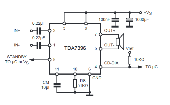
We apply +Vs to leg 8, and nothing to leg 4. Therefore, the diagram will look like this:

Vs is the supply voltage. It can be from 8 to 18 Volts. “IN+” and “IN-” – we send a weak sound signal here. We attach a speaker to the 5th and 7th legs. We set the sixth leg to minus.
Here is my wall mounted assembly

I did not use capacitors at the power input of 100nF and 1000uF, since I already have pure voltage coming from the power supply.
I rocked the speaker with the following parameters:

As you can see, the coil resistance is 4 ohms. The frequency band indicates that it is a subwoofer type.
And this is what my sub in a self-made housing looks like:

I tried to take a video, but the sound on the video is very poor. But I can still say that the phone at medium power was already hammering so hard that my ears were turning, although the consumption of the entire circuit in working form was only about 10 watts (multiply 14.3 by 0.73). In this example, I took the voltage as in a car, that is, 14.4 Volts, which is well within our operating range from 8 to 18 Volts.

If you do not have a powerful power source, then you can assemble it according to this diagram.
Don't get hung up on this particular chip. These TDA chips, as I already said, there are many types. Some of them amplify the stereo signal and can output sound to 4 speakers at once, as is done in car radios. So don’t be lazy to scour the Internet and find a suitable TDA. After completing the assembly, let your neighbors check out your amplifier by turning the volume knob all the way to the balalaika and leaning the powerful speaker against the wall).
But in the article I assembled an amplifier using a TDA2030A chip

It turned out very well, since the TDA2030A has better characteristics than the TDA7396
For variety, I’ll also attach another diagram from a subscriber whose TDA 1557Q amplifier has been working properly for more than 10 years in a row:

Amplifiers on Aliexpress
I also found kit kits on Ali on TDA. For example, this stereo amplifier is 15 watts per channel and costs $1. This power is quite enough to hang out in your room listening to your favorite tracks.

You can buy it.
And here it's ready right away

And in general, there are a lot of these amplifier modules on Aliexpress. Click on this link and choose any amplifier you like.