How to assemble a tesla generator at home. The Tesla generator is an ideal source of energy. Step-by-step instructions for making a coil
June 19, 2014 at 04:41Tesla coil from hozmag
- DIY or DIY
Having a pathological craving for plumbing fittings, I just can’t accustom myself to use it for its intended purpose. Ideas always come into my head what to make from pipes, fittings and adapters so that they will never be used in plumbing again. That is what happened this time as well. We make a Tesla high-voltage generator on sanitary fittings.
Why such a choice? Everything is very simple. I am a supporter of elegant and well-reproducible technical solutions. A minimum of locksmith, finishing, dopilki, doklepki. Life should please with ease of decisions and elegance of forms.
What will be needed?
The store had everything in stock and the purchase took just a few minutes.
Everything you need is in the picture. I give the original names from store labels
1. Pipe 40x0.25m
2. Adapter ring for pipe 40mm
3. Varnish high-voltage (was in the arsenal)
4. Coupling transition to the smooth end of the cast-iron pipe 50mm
5. Rubber cuff for 50mm
6. Copper wire 0.14mm PEV-2 (from old stocks)
The cost of all fittings is about 200 rubles. When buying, it is better to choose a larger store so as not to explain to security guards and managers why you connect non-connectable elements to each other and how to help you find what you need. We also need a few more inexpensive parts, about which a little later. But first, let's digress a bit...
Tesla coils and stuff
Much has been said about Tesla, but for the most part people (including me) are unanimous in their opinion - Tesla did a lot for the development of science and technology for his time. Many of his patents have come to life, while some still remain beyond understanding of the essence. But the main merits of Tesla can be considered the study of the nature of electricity. Especially high voltage. Tesla impressed his friends and colleagues with amazing experiments in which he easily and fearfully controlled high-voltage generators that produced hundreds of thousands, and sometimes millions of volts. In this article, I describe the manufacture of a miniature Tesla generator, the theory of which has been studied quite well and in detail. And now to business!
What should we get?
In the end, we must assemble our device as shown in the photo:
Step 1. Winding the high voltage coil
We wind the main high-voltage coil on the tube with a wire of 0.1-0.15 mm. I had 0.14 mm wire in stock. This is perhaps the most boring job. Winding must be done as carefully as possible, turn to turn. You can use a rig, but I wound the coils by hand. By the way, I always do something in at least two copies. Why? First, the skill. The second product turns out to be just sweet, and there will always be a person who will start begging for the device (give it, sell it, let it be used, etc.). I give away the first, the second remains in the collection, the eye rejoices, friendship grows stronger, harmony in the world grows.

Step 2: Insulating the High Voltage Coil
The next important step is to isolate the high voltage coil. I will not say that the coil must be soaked 20 times with wax, wrapped in varnished cloth or boiled in oil. All these are Kolchak's approaches. We are modern people, so we use high-voltage varnish (see the first photo. I don’t indicate the brand of varnish, you can google it) and wide heat shrink. Lacquered in two or three layers. Dry the layer for at least 20-30 minutes. The varnish applies beautifully. The result is great! The coil becomes simply eternal! The cost of varnish is not great. Three hundred rubles balloon. I think it's enough for a dozen of these devices. BUT!!!
Varnish turned out VERY TOXIC! Literally a minute later, my head ached and the cat began to vomit. The work had to be stopped. Immediately ventilate the room, stop the application of varnish. I had to rush to the store. I buy beer, and milk for the cat to recover from poisoning:

For a good application of varnish should be done under the hood, but (after saving myself and the cat) I did it on the street. Fortunately, the weather was favorable, there was no wind and dust, and it did not rain. Then you need to put on a wide heat shrink and seat the coil with a hot air gun. This must be done carefully, from the middle to the edges. It should be tight and even.
Step 3. Making the inductor and assembling the entire structure
Perhaps the most critical part of the generator. I have analyzed many designs of such devices and many authors make the same mistake. Firstly, a fairly thin wire is used, and secondly, there is no uniform and significant (at least 1 cm) gap with a high-voltage coil and many turns are used. This is completely unnecessary. Enough 2..4 turns in the first third of the high-voltage coil. For the inductor, we use a hollow copper annealed tube with a diameter of 8 mm, which ensures minimal inductance and simply excellent generator performance during operation. We wind three turns on a rubber cuff into the grooves. To prevent the tube from breaking, fill it tightly with fine sand. Then carefully pour out the sand. After collecting the whole structure, everything should look like in the photo:

The copper tube is perhaps the most expensive item in this homemade product. As much as 150 rubles. Also bought from a hardware store.
Some subtleties...
The subtleties are related to the design of the inductor contacts. They are made of annealed copper strip and closed with heat shrink. This ensures the minimum inductance of the structure, which is very important. The contacts are hidden inside the coupling. All connections should be as short as possible and made with wide copper strips, which reduces various losses. We put on an adapter-ring on top of the device, which presses the copper round contact, on which the upper output of the high-voltage coil is soldered. The structure at the top is filled with liquid rubber. There is a mini-jack in the center.

Step 4. Connecting and testing the generator
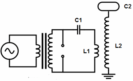
There are approximately 2 million ways to power such a device. Let's stop at the simplest - using the diagram shown in this figure:

You will need a couple of resistors, a capacitor, do not forget to put the transistor on the radiator. Ratings are indicated. The resource of the circuit, I think, is not large, but given the cheapness of transistors and the urgency of the desire to see the result, this no longer counts.

If everything is assembled correctly, the circuit will work immediately. If there is no generation, then switch the contacts of the inductor vice versa. It worked for me right away. Generation starts from 5-7 volts. Already at 6 volts, the generation is stable, at 12 volts everything is burning around. In the photo you can see that the whole structure is blown by a fan, since the transistor heats up pretty much, although it is placed on a radiator. Surprisingly, the scheme is very reliable. At 12 volts it works for hours and is very stable. When the light is off and the "dead" light bulb shines brightly. It is better to take a more powerful power source for the coil (with an output current of at least 2-3 amperes).

Video of the device can be viewed
Today, a Tesla transformer is called a high-frequency high-voltage resonant transformer, and many examples of striking implementations of this unusual device can be found on the network. A coil without a ferromagnetic core, consisting of many turns of thin wire, topped with a torus, emits real lightning, impressing astonished spectators. But does everyone remember how and why this amazing device was originally created?
The history of this invention begins at the end of the 19th century, when a brilliant experimental scientist, working in the USA, only set himself the task of learning how to transmit electrical energy over long distances without wires.
It is hardly possible to indicate the exact year when this idea came to the scientist, but it is known that on May 20, 1891, Nikola Tesla gave a detailed lecture at Columbia University, where he presented his ideas to the staff of the American Institute of Electrical Engineers, and illustrated something, showing illustrative experiments.
The purpose of the first demonstrations was to show a new way of obtaining light by using high frequency and high voltage currents for this, and also to reveal the features of these currents. In fairness, we note that modern energy-saving fluorescent lamps work precisely on the principle that Tesla proposed to produce light.

The final theory regarding exactly loomed gradually, the scientist spent several years of his life, bringing his technology to mind, experimenting a lot and painstakingly improving each element of the circuit, he developed interrupters, invented resistant high-voltage capacitors, invented and modified circuit controllers, but he could not realize his plan to life in the scale in which he wanted.
However, the theory has reached us. Diaries, articles, patents and lectures by Nikola Tesla are available, in which you can find the initial details regarding this technology. The principle of operation of a resonant transformer can be found by reading, for example, Nikola Tesla's patents No. 787412 or No. 649621, already available online today.
If you try to briefly understand how the Tesla transformer works, consider its device and principle of operation, then there is nothing complicated about it.
The secondary winding of the transformer is made of insulated wire (for example, enamel wire), which is laid turn to turn in one layer on a hollow cylindrical frame, the ratio of the height of the frame to its diameter is usually taken from 6 to 1 to 4 to 1.
After winding, the secondary winding is coated with epoxy resin or varnish. The primary winding is made of a wire of a relatively large cross section, it usually contains from 2 to 10 turns, and is laid in the form of a flat spiral, or wound like a secondary winding - on a cylindrical frame with a diameter slightly larger than that of the secondary.
The height of the primary winding, as a rule, does not exceed 1/5 of the height of the secondary. A toroid is connected to the upper terminal of the secondary winding, and its lower terminal is grounded. Next, let's look at everything in more detail.
For example: the secondary winding is wound on a frame with a diameter of 110 mm, with a PETV-2 enamel wire with a diameter of 0.5 mm, and contains 1200 turns, so its height is approximately 62 cm, and the length of the wire is about 417 meters. Let the primary winding contain 5 turns of a thick copper tube wound on a diameter of 23 cm and have a height of 12 cm.

Next, a toroid is made. Its capacitance should ideally be such that the resonant frequency of the secondary circuit (grounded secondary coil together with the toroid and the environment) would correspond to the length of the wire of the secondary winding so that this length would be equal to a quarter of the wavelength (for our example, the frequency is 180 kHz) .
For an accurate calculation, a special program for calculating Tesla coils, such as VcTesla or inca, can be useful. A high-voltage capacitor is selected to the primary winding, the capacitance of which, together with the inductance of the primary winding, would form an oscillatory circuit, the natural frequency of which would be equal to the resonant frequency of the secondary circuit. Usually they take a capacitor close in capacity, and the setting is carried out by selecting the turns of the primary winding.
The essence of the Tesla transformer in its canonical form is as follows: the primary circuit capacitor is charged from a suitable high voltage source, then it is connected by a switch to the primary winding, and this is repeated many times per second.
As a result of each switching cycle, damped oscillations occur in the primary circuit. But the primary coil is an inductor for the secondary circuit, therefore electromagnetic oscillations are excited accordingly in the secondary circuit.
Since the secondary circuit is tuned to resonance with the primary oscillations, a voltage resonance occurs on the secondary winding, which means that the transformation ratio (the ratio of the turns of the primary winding and the turns of the secondary winding covered by it) must also be multiplied by Q - the quality factor of the secondary circuit, then the value of the real ratio will be obtained voltage on the secondary winding to the voltage on the primary.
And since the length of the wire of the secondary winding is equal to a quarter of the wavelength of the oscillations induced in it, it is on the toroid that the voltage antinode will be located (and at the ground point - the current antinode), and it is there that the most effective breakdown can take place.
Different schemes are used to power the primary circuit, from a static spark gap (arrester) powered by MOTs (MOT - high-voltage transformer from a microwave oven) to resonant transistor circuits on programmable controllers powered by rectified mains voltage, but the essence of this does not change.
Here are the most common types of Tesla coils, depending on how they are driven:
SGTC (SGTC, Spark Gap Tesla Coil)- Tesla transformer on the spark gap. This is a classic design, a similar scheme was originally used by Tesla himself. A surge arrester is used here as a switching element. In low-power designs, the arrester consists of two pieces of thick wire located at some distance, and in more powerful designs, complex rotating arresters are used using motors. Transformers of this type are made if only a large streamer length is required, and efficiency is not important.
VTTC (VTTC, Vacuum Tube Tesla Coil)- Tesla transformer on an electronic lamp. A powerful radio tube, for example GU-81, is used here as a switching element. Such transformers can operate continuously and produce fairly thick discharges. This type of power supply is most often used to build high-frequency coils, which, due to the typical appearance of their streamers, are called “torch coils”.
SSTC (SSTC, Solid State Tesla Coil)- Tesla transformer, in which semiconductors are used as a key element. Usually this . This type of transformer can operate continuously. The appearance of the streamers created by such a coil can be very different. This type of Tesla transformer is easier to control, for example, you can play music on them.
DRSSTC (DRSSTC, Dual Resonant Solid State Tesla Coil)- Tesla transformer with two resonant circuits, here, as in SSTC, semiconductors are used as keys. DRSSTC is the most difficult type of Tesla transformers to manage and configure.
To obtain more efficient and effective operation of the Tesla transformer, it is the DRSSTC topology schemes that are used, when a powerful resonance is achieved in the primary circuit itself, and in the secondary, respectively, a brighter picture, longer and thicker lightning (streamers).
Tesla himself, as best he could, tried to achieve just such an operating mode of his transformer, and the rudiments of this idea can be seen in patent No. resonance. You can read about these experiments of the scientist in his diary (the scientist's notes about the experiments in Colorado Springs, which he conducted from 1899 to 1900, have already been published in printed form).
Speaking about the practical application of the Tesla transformer, one should not be limited only to admiring the aesthetic nature of the discharges received, and treat the device as a decorative one. The voltage on the secondary winding of the transformer can reach millions of volts, it is, after all, an efficient source of ultra-high voltage.

Tesla himself developed his system for transmitting electricity over long distances without wires, using the conductivity of the upper air layers of the atmosphere. It was assumed that there was also a receiving transformer of a similar design, which would lower the received high voltage to a value acceptable to the consumer, you can find out about this by reading Tesla's patent No. 649621.
The nature of the interaction of the Tesla transformer with the environment deserves special attention. The secondary circuit is an open circuit, and the system is not thermodynamically isolated, it is not even closed, it is an open system. Modern research in this direction is being carried out by many researchers, and the point on this path has not yet been set.
Andrey Povny
Tesla coil
Discharges from the wire on the terminal
Tesla transformer- the only one of Nikola Tesla's inventions bearing his name today. This is a classic resonant transformer, producing high voltage at high frequency. It was used by Tesla in several sizes and variations for his experiments. The Tesla Transformer is also known as the Tesla Coil. Tesla coil). The following abbreviations are often used in Russia: TS (from Tesla coil), CT (Tesla coil), just Tesla and even affectionately - Katka. The device was claimed by patent No. 568176 dated September 22, 1896, as "Apparatus for the production of electric currents of high frequency and potential."
Design Description
![]()
Scheme of the simplest Tesla transformer
In its elementary form, the Tesla transformer consists of two coils, primary and secondary, and a harness consisting of a spark gap (breaker, the English version of Spark Gap is often found), a capacitor, a toroid (not always used) and a terminal (shown as an “output” in the diagram) .
The primary coil is built from 5-30 (for VTTC - Tesla coil on a lamp - the number of turns can reach 60) turns of large diameter wire or copper tube, and the secondary of many turns of smaller diameter wire. The primary coil can be flat (horizontal), conical or cylindrical (vertical). Unlike many other transformers, there is no ferromagnetic core here. Thus, the mutual inductance between the two coils is much less than conventional transformers with a ferromagnetic core. This transformer also has practically no magnetic hysteresis, the phenomenon of delay in the change in magnetic induction relative to the change in current, and other disadvantages introduced by the presence of a ferromagnet in the field of the transformer.
The primary coil together with the capacitor forms an oscillatory circuit, which includes a non-linear element - a spark gap (spark gap). The arrester, in the simplest case, is an ordinary gas one; usually made of massive electrodes (sometimes with radiators), which is made for greater wear resistance when high currents flow through an electric arc between them.
The secondary coil also forms an oscillatory circuit, where the capacitive coupling between the toroid, the terminal device, the turns of the coil itself and other electrically conductive elements of the circuit with the Earth performs the role of a capacitor. The terminal device (terminal) can be made in the form of a disk, a sharpened pin or a sphere. The terminal is designed to produce long, predictable sparks. The geometry and relative position of the parts of the Tesla transformer greatly affects its performance, which is similar to the problem of designing any high-voltage and high-frequency devices.
Functioning
The Tesla transformer of the simplest design under consideration, shown in the diagram, operates in a pulsed mode. The first phase is the charge of the capacitor up to the breakdown voltage of the arrester. The second phase is the generation of high-frequency oscillations.
Charge
The capacitor is charged by an external high voltage source, protected by chokes and usually built on the basis of a step-up low-frequency transformer. Since part of the electrical energy accumulated in the capacitor will go to the generation of high-frequency oscillations, they try to maximize the capacitance and the maximum voltage on the capacitor. The charge voltage is limited by the breakdown voltage of the spark gap, which (in the case of an air gap) can be adjusted by changing the distance between the electrodes or their shape. The typical maximum capacitor charge voltage is 2-20 kilovolts. The sign of the voltage for the charge is usually not important, since electrolytic capacitors are not used in high-frequency oscillatory circuits. Moreover, in many designs, the sign of the charge changes with the frequency of the household power supply (or Hz).
Generation
After reaching the breakdown voltage between the electrodes of the arrester, an avalanche-like electrical breakdown of the gas occurs in it. The capacitor is discharged through the arrester to the coil. After the discharge of the capacitor, the breakdown voltage of the arrester decreases sharply due to the charge carriers remaining in the gas. In practice, the circuit of the oscillatory circuit of the primary coil remains closed through the spark gap, as long as the current creates a sufficient number of charge carriers to maintain the breakdown voltage substantially lower than the amplitude of the oscillation voltage in the LC circuit. The oscillations are gradually damped, mainly due to losses in the spark gap and the escape of electromagnetic energy to the secondary coil. Resonant vibrations occur in the secondary circuit, which leads to the appearance of a high-voltage high-frequency voltage at the terminal!
As an RF voltage generator, modern Tesla transformers use tube (VTTC - Vacuum Tube Tesla Coil) and transistor (SSTC - Solid State Tesla Coil, DRSSTC - Dual Resonance SSTC) generators. This makes it possible to reduce the dimensions of the installation, increase controllability, reduce the noise level and get rid of the spark gap. There is also a variety of Tesla transformers, powered by direct current. The abbreviations of the names of such coils contain the letters DC, for example DC DRSSTC. Tesla's magnifer coils are also included in a separate category.
Many developers use controlled electronic components as an interrupter (arrester), such as transistors, MOSFET transistor modules, vacuum tubes, thyristors.
Tesla transformer use

Tesla transformer discharge

Discharge from the end of the wire
The output voltage of a Tesla transformer can reach several million volts. This voltage at the resonant frequency is capable of creating impressive electric discharges in the air, which can be many meters long. These phenomena fascinate people for various reasons, so the Tesla transformer is used as a decorative item.
The transformer was used by Tesla to generate and propagate electrical oscillations aimed at controlling devices at a distance without wires (radio control), wireless data transmission (radio), and wireless power transmission. At the beginning of the 20th century, the Tesla transformer also found popular use in medicine. Patients were treated with weak high-frequency currents, which, flowing through a thin layer of the skin surface, do not harm internal organs (see Skin effect), while exerting a tonic and healing effect. Recent studies of the mechanism of action of powerful HF currents on a living organism have shown the negativity of their influence.
Today, the Tesla transformer does not have a wide practical application. It is made by many lovers of high-voltage technology and the effects that accompany it. It is also sometimes used to ignite discharge lamps and to find leaks in vacuum systems.
The Tesla transformer is used by the military to quickly destroy all electronics in a building, tank, ship. A powerful electromagnetic pulse is created for a fraction of a second within a radius of several tens of meters. As a result, all microcircuits and transistors, semiconductor electronics burn out. This device operates completely silently. A message appeared in the press that the current frequency reaches 1 Terahertz.
Effects observed during the operation of the Tesla transformer
During operation, the Tesla coil creates beautiful effects associated with the formation of various types of gas discharges. Many people collect Tesla transformers in order to look at these impressive, beautiful phenomena. In general, the Tesla coil produces 4 types of discharges:
- Streamers (from English. Streamer) - dimly glowing thin branched channels that contain ionized gas atoms and free electrons split off from them. It flows from the terminal (or from the sharpest, curved BB-parts) of the coil directly into the air, without going into the ground, since the charge flows evenly from the discharge surface through the air into the ground. The streamer is, in fact, the visible ionization of air (glow of ions) created by the HV field of the transformer.
- Spark (from English. Spark) is a spark discharge. Goes from the terminal (or from the most sharp, curved BB parts) directly into the ground or into a grounded object. It is a bundle of bright, rapidly disappearing or replacing each other filamentous, often highly branched strips - spark channels. There is also a special kind of spark discharge - a sliding spark discharge.
- Corona discharge - the glow of air ions in a high voltage electric field. Creates a beautiful bluish glow around the BB parts of the structure with a strong surface curvature.
- Arc discharge - formed in many cases. For example, with sufficient power of the transformer, if a grounded object is brought close to its terminal, an arc may ignite between it and the terminal (sometimes you need to directly touch the object to the terminal and then stretch the arc, retracting the object to a greater distance). This is especially true of Tesla tube coils. If the coil is not strong enough and reliable enough, then the provoked arc discharge can damage its components.
You can often observe (especially near powerful coils) how discharges go not only from the coil itself (its terminal, etc.), but also towards it from grounded objects. Also, corona discharge can occur on such objects. Rarely, a glow discharge can also be observed. It is interesting to note that different chemicals applied to the discharge terminal can change the color of the discharge. For example, sodium changes the usual spark color to orange, and bromine to green.
The operation of a resonant transformer is accompanied by a characteristic electrical crackle. The appearance of this phenomenon is associated with the transformation of streamers into spark channels (see the article spark discharge), which is accompanied by a sharp increase in the current strength and the amount of energy released in them. Each channel rapidly expands, the pressure rises abruptly in it, as a result of which a shock wave arises at its boundaries. The combination of shock waves from the expanding spark channels generates a sound perceived as a "crack" of a spark.
Unknown Tesla Transformer Effects
Many people believe that Tesla coils are special artifacts with exceptional properties. There is an opinion that Tesla's transformer can be a generator of free energy and is a perpetual motion machine, based on the fact that Tesla himself believed that his generator takes energy from the ether (a special invisible matter in which electromagnetic waves propagate) through a spark gap. Sometimes you can hear that with the help of the "Tesla Coil" you can create anti-gravity and effectively transmit electricity over long distances without wires. These properties have not yet been tested and confirmed by science. However, Tesla himself said that such abilities would soon be available to mankind with the help of his inventions. But later I thought that people are not ready for this.
Also very common is the thesis that the discharges emitted by Tesla transformers are completely safe and can be touched by hands. This is not entirely true. In medicine, "Tesla coils" are also used to heal the skin. This treatment has positive results and has a beneficial effect on the skin, but the design of medical transformers is very different from the design of conventional ones. Therapeutic generators are distinguished by a very high frequency of the output current, at which the thickness of the skin layer (see Skin effect) is safely small, and by extremely low power. And the thickness of the skin layer for an average Tesla coil is from 1 mm to 5 mm, and its power is enough to heat up this skin layer and disrupt natural chemical processes. With prolonged exposure to such currents, serious chronic diseases, malignant tumors and other negative consequences can develop. In addition, it should be noted that being in the HF explosive field of the coil (even without direct contact with the current) can adversely affect health. It is important to note that the human nervous system does not perceive high-frequency current and pain is not felt, but nevertheless this can initiate processes that are detrimental to a person. There is also a risk of poisoning by gases generated during the operation of the transformer in a closed room without fresh air. Plus, you can get burned, since the discharge temperature is usually enough for a small burn (and sometimes for a big one), and if a person still wants to “catch” the discharge, then this should be done through some kind of conductor (for example, a metal rod) . In this case, there will be no direct contact of the hot discharge with the skin, and the current will first flow through the conductor and only then through the body.
Tesla transformer in culture
In the Jim Jarmusch film Coffee and Cigarettes, one of the episodes is based on the demonstration of the Tesla transformer. In the story, Jack White, guitarist and vocalist of The White Stripes, tells Meg White, the band's drummer, that the earth is a conductor of acoustic resonance (the theory of electromagnetic resonance is an idea that has occupied Tesla's mind for many years), and then "Jack demonstrates Meg Tesla's car."
In Command & Conquer: Red Alert, the Soviet side can build a defensive structure in the form of a tower with a spiral wire that strikes the enemy with powerful electric discharges. Even in the game there are tanks and foot soldiers using this technology. Tesla coil (in one of the translations - Tesla tower) is an extremely accurate, powerful and long-range weapon in the game, but it consumes a relatively high amount of energy. To increase the power and range of destruction, you can "charge" the towers. To do this, give the order to the Tesla Warrior (this is an infantryman) to come up and stand next to the tower. When the warrior reaches the place, he will start charging the tower. In this case, the animation will be similar to when attacking, but the lightning from his hands will be yellow.
The Tesla coil, which bears the name of the inventor, is an oscillating circuit that consists of two coils. It allows you to get a current of high denomination and frequency.
So what do we need:
- switch;
- 22 kOhm resistor;
- transistor 2N2222A;
- crown connector;
- PVC pipe 8.5 cm long and 2 cm in diameter;
- 9 volt crown;
- copper wire with a cross section of 0.5 mm;
- a piece of laminate;
- glue gun;
- soldering iron;
- a small piece of wire 15 cm long.

First of all, we must wind the copper wire around the PVC tube, departing from the edges by about 0.5 cm. In order to prevent the wire from unwinding at first, the author of the idea advises fixing its end with paper tape.


After the wire is wound, we also fix the second end with paper tape so that the wire does not wind up. Cut the end of the wire with wire cutters. The coil is ready.


Now you need to glue it to the base of a piece of laminate with a glue gun.


On a piece of laminate, we also glue a switch, a transistor and a crown connector.


Let's move on to wiring. We solder the lower copper wire coming from the coil to the middle contact on the transistor.


We also solder a resistor to the middle contact.

We need a piece of wire for the secondary winding. We wrap it twice around the coil and fix both ends of the wire with hot glue on the base.


We solder the upper end of the secondary winding wire to the free end of the resistor.


We solder the second end of the wire of the secondary winding to the right contact on the transistor. To facilitate the work, you can use short lengths of wiring.

Next, the contacts from the resistor, together with the wire from the secondary winding, are soldered to the contact from the switch.
You can make a generator that is powered by daylight. This is an excellent analogue of a solar panel, but the main advantage of such a generator is a minimum of materials, low cost and ease of assembly. Of course, such a generator will produce much less energy than a solar panel, but you can make a lot of them and thus get a good influx of free energy.
Nikola Tesla believed that the whole world is energy, thus, to receive and use it, it is enough just to assemble a device that could capture this free energy. He had many different designs for "fuelless" generators. One of them, which today everyone can do with their own hands, will be discussed below.


The principle of operation of the device is that it uses the energy of the earth as a source of negative electrons, and the energy of the sun (or any other light source) as a source of positive electrons. As a result, there is a potential difference, which forms an electric current.
In total, the system has two electrodes, one is grounded, and the other is placed on the surface and captures energy sources (light sources). A large capacitor acts as a storage element. However, nowadays the capacitor can also be replaced with a lithium-ion battery by connecting it through a diode so that the opposite effect does not occur.
Materials and tools for the manufacture of the generator:
- foil;
- a sheet of cardboard or plywood;
- wires;
- high-capacity capacitor with high operating voltage (160-400 V);
- resistor (presence is optional).

Manufacturing process:
Step one. We make grounding
First you need to make a good ground. If the homemade product will be used in a country house or village, then you can drive a metal pin deeper into the ground, this will be grounding. You can also connect to existing metal structures that go into the ground.
If you use such a generator in an apartment, then here you can use water and gas pipes as grounding. All modern sockets are also grounded; you can also connect to this contact.

Step two. Making a receiver of positive electrons
Now we need to make a receiver that could capture those free, positively charged particles that are produced along with the light source. Such a source can be not only the sun, but also already working lamps, various lamps, and the like. According to the author, the generator generates energy even in daylight in cloudy weather.
The receiver consists of a piece of foil that is attached to a piece of plywood or cardboard. When light particles "bombard" an aluminum sheet, currents are formed in it. The larger the foil area, the more energy the generator will produce. To increase the power of the generator, several such receivers can be built and then all of them connected in parallel.

Step three. Connecting the circuit
At the next stage, you need to connect both contacts to each other, this is done through a capacitor. If we take an electrolytic capacitor, then it is polar and has a designation on the case. To the negative contact, you need to connect the ground, and to the positive, the wire going to the foil. Immediately after that, the capacitor will begin to charge and you can then remove electricity from it. If the generator turns out to be too powerful, then the capacitor may explode from an excess of energy, in connection with this, a limiting resistor is included in the circuit. The more charged the capacitor, the more it will resist further charging.
As for the conventional ceramic capacitor, their polarity does not matter.


Among other things, you can try to connect such a system not through a capacitor, but through a lithium battery, then it will be possible to accumulate much more energy.

That's all, the generator is ready. You can take a multimeter and check what voltage is already in the capacitor. If it is high enough, you can try connecting a small LED. Such a generator can be used for various projects, for example, for autonomous LED night lighting lamps.
In principle, other materials, such as copper or aluminum sheets, can be used instead of foil. If someone in a private house has a roof made of aluminum (and there are many of them), then you can try to connect to it and see how much energy will be generated. It will also be a good idea to check whether such a generator can generate energy if the roof is metal. Unfortunately, there were no figures that would show the current strength in relation to the area of the receiving contact.