Konon soldering symmetrical and asymmetrical. Connecting cables and connectors. Qualitative characteristics of various audio cables
Let's touch on the topic of home recording studio switching. In addition to all the musical equipment that we considered earlier, we also need a good cable switching system. That is, the connection of all musical equipment with a cable. Most novice sound engineers do not attach much importance to this, as they consider it to be the last thing. But in fact, this is a gross mistake.
Believe it or not, I am fully convinced that the sound quality in any class of studio depends on the quality of the switching. This was tested repeatedly in a variety of studios and equipment. Thus, a simple conclusion can be drawn. It is impossible to achieve good results with an illiterate and poor-quality connection of musical equipment. It is for this reason that below I will cover all the key points of switching in a home recording studio.
Cable types
All cables that are used in a recording studio are divided into two types:
- Balanced or balanced cables- contain two signal cables and one metal braid.
- Unbalanced or asymmetrical- contain one signal cable and one metal braid.
I think you should use balanced cables in your studio. They are called so because they are soldered equally from both ends and their signal cores are not mixed up in places. This decoupling has the advantage of less noise that arises from various pickups.
Types of connectors
Let's look at the types of connectors we need. But first, you need to understand the components:
- Nest- this is where the cable is connected;
- Plug is what is connected.
There are 4 types of connectors that are used in a recording studio:
Jack (may be referred to as fat or big jack)- its size is 6.3 mm. It is also referred to as 1.4 inches. The jack plug can be two-pin and three-pin. Two-pin (TS) derived from (Tip) (3), that is, the tip and (Sleeve) (1), that is, the sleeve itself. It's all separated by a plastic black ring (4) . In fact, there are two contacts here - type and sleeve. As for the three pin jack (TRS), then there is Tip (3) Sleeve (1) and additionally added Ring (ring in plug) (2), to which the contact of the pro-channel or the inverted phase of the signal fits.
Three-pin jacks are used not only as stereo, but also as balanced mono cables with a certain pinout. That is, if a three-pin jack can be used in mono and stereo, then a two-pin jack can only be used as a mono jack. The jack connector is usually used when connecting a guitar, keyboards (e.g. synthesizer), as well as sound effects processors. Another such stereo jack connector can be used for balanced to a sound card and connecting a headphone amplifier to it. In fact, this is a pretty universal connector.

- this connector, except for the size, is no different. There are both two-pin and three-pin. In a professional environment, minijack is probably only used in . Therefore, we will not dwell on it in more detail.

Canon XLR (XLR3)- This is a professional connector and is usually not used in consumer audio equipment. Represents a metal (sometimes plastic) three pin connector. As with the jack, these pins correspond to three pins: sleeve, tip, and ring. With the help of such an xlr connector, a fairly large amount of studio equipment is switched. For example, monitors, a preamp with a microphone, as well as a microphone with a mixing console, with an audio interface, and much more.
(tulip connector)- it is often found in consumer equipment, but can be found on some budget sound cards or monitors. Usually two connectors are used (left and right channels). In professional recording studios, tulips are mostly used as S/PDIF digital interface connectors. Sometimes they are also found on as outputs for a recording device. But still very often such a connector is found precisely in household appliances and video equipment.
Cable wiring diagram
I will not consider the cable desoldering scheme, as it is very long. But we simply cannot leave such an important topic unattended. Therefore, I am attaching graphical wiring diagrams for all the necessary connecting cables and wiring diagrams for switching various equipment in a home recording studio. Click on image to enlarge.
You ask: “Why solder at all? Why can't you buy ready-made connecting cables? Yes, you can buy ready-made ones. But the problem is that not all cables are easy to find. And ready-made soldered ones will cost you more than buying a separate cable, plugs and further wiring. Another advantage is that you can buy a cable of exactly the required length.
But there are also disadvantages here. The fact is that not everyone knows how to solder well. In this case, there remains one most optimal option - to buy the necessary cable and plugs separately. And then give it all to a professional who will solder everything with high quality. It is beneficial in every way.
Now I want to give you some tips for switching in your home recording studio. You must memorize and follow them as much as possible. Here are the recommendations:
- Use only high quality cables and connectors. Don't skimp on this. Of course, it would be pointless to buy a cable worth several tens of dollars per meter for less budget equipment. But buying fake and low-quality products for a couple of rubles per meter from unknown manufacturers is also not an option. I trust manufacturers like Klotz and Proel.
- Use the same cables to connect the same components. For example, when connecting monitors to an audio interface, each of them must be connected to the interface with the same cable. Moreover, both in length and wiring, and in the manufacturer's company and even the model itself.
- Choose a balanced connection. This connection gives much less noise that comes from various interference and allows the use of longer cables.
- Prefer to connect using XLR connectors whenever possible. They have better features than the rest. But if you do not have such an opportunity, for example, when the outputs of the audio interface are used jack, and jack and xlr are used at the input, then use a jack to jack cable.
- If you decide to solder the cables yourself, be very careful not to mix up the signal cores. Otherwise, such a thing as antiphase may occur, and when recording a stereo signal, in this case, the sound will not be heard at all. And during playback, the sound will be mutually suppressed, that is, one channel will eat the other. Therefore, if you decide to solder the cable yourself, then follow the diagrams that are attached in this article.
This concludes our discussion of the topic. Now you know what switching should be like in a home recording studio. You already know what type of cable is best to use, what types of connectors and cable wiring diagrams are. Also at the end, I gave you some useful tips for switching cables in the studio. Make sure to follow them.
Open systems, private terms
Systems will not become open as long as private terms are used in their creation and operation. The vagueness of terms affects the quality of services of the Russian cable systems market, which includes thousands of firms, tens of thousands of specialists and many times more users.
Transmission medium
Structured cabling systems (SCS) of office buildings are now becoming the same natural engineering subsystems as power wiring. More and more people use network technologies, including professionally.
Open systems standards appeared in 1991, and a few months later SCS began to be installed in our country. During this time, the frequency range of electrically conductive systems has expanded from 1 to 100 MHz. New category standards are being developed with a range of 200 and 600 MHz. The data transfer speed has increased to 1000 Mbps. Category standards appear every four years. Symmetrical electrically conductive cables have properties that no one could have even dreamed of ten years ago. Products and technologies are updated rapidly.
Standards allow you to move from private to open systems that have unified parameters and support the operation of equipment from any manufacturer. The difference between SCS and equipment is that they are created by thousands and tens of thousands of independent organizations, always in a single copy and always at their own discretion. Component manufacturers who provide multi-year warranties for such systems control a very small percentage of installations.
The quality and conformity of systems cannot be achieved without knowing the basics of their construction and a common understanding of the categories. The importance of precise terminology is evidenced by the fact that all SCS standards begin with a glossary of definitions and a list of abbreviations. Cabling documentation has been in use for ten years or more. Therefore, cabling terminology needs to be sorted out first. The state here is more than deplorable: mass myths and illusions prevail. Obvious concepts are mixed up, there is a lot of confusion, and there are almost as many options for delimiting SCS into subsystems and functional elements as there are projects.
cable jargon
The terminology for Structured Cabling Systems (SCS) is mostly American. International standards not only appear later, but have not yet been adopted in areas such as cabling, administration, grounding, metering, centralized architecture, open offices, etc.
A feature of a number of American terms is that they reflect the visual and sometimes secondary properties of objects. For an elementary understanding of what is at stake, pictures are required. The existence of such terms is impossible without illustrations and visual demonstrations.
The difficulty of translating incomprehensible words leads to the emergence of jargon. The problem is that in the original American language a number of terms are surprisingly unfortunate. The meaning of some terms is far from the real content and actual meaning. Examples of the most common jargon are shown in Table 1.
Table 1. Terms, their meaning and actual meaning
| Professional term | The meaning of the word | actual value |
|---|---|---|
| patch cord | stitch cable | patch cable |
| balun | balrazbal ( ball ans- messed up ans) | wave adapter |
| shotgun | shotgun | double cable |
| harmonic | harmonic | comb (connector) |
| termination | termination | connectors |
| octopus | octopus | splitter |
| backbone | ridge | highway |
| campus | campus | building complex) |
Western terms that fix secondary features are not so bad. Very often understandable and easily translatable words are used in foreign transcription or transliteration. Among them: demorack (demonstration stand), plenum (air duct), conduit (pipeline), rodents (rodents), adhesive (glue). They enter the spoken language from articles, prospectuses, price tags, and even SCS manuals published as books.
Moreover, the authors of textbooks and articles record the capitulation of their own possibilities of using the Russian language, moving on to interspersing terms and abbreviations in English. For example, cables UTP, STP, powersum, hybrid, plenum, riser, zip-cord, highway HC-IC, contact IDC, Light-emitting diode LED, technology fiber to the desk, system air-blown fibers etc., etc. Such specialists want to convey their ideas to colleagues, but do not care about making them easier to understand. Perhaps they believe that readers know a foreign language better and will figure it out themselves. It is also natural that such authors spread their own delusions.
Connector - connector - socket
Examples of how a polysemantic word connector led to the confusion of different concepts in professional terminology, are found in almost every article where this term is mentioned, and in most projects. To designate the framework, let's turn to the dictionary entry.
Connector - the end of a cable for a switched electrical or optical connection. Connector - an element of a cable connector that provides electrical connection of conductors. In other words, in order to connect cables to each other, two types of electrical contacts are needed: one-piece - for conductors, and detachable - for connecting two cables. The most common way to permanently connect symmetrical conductors in SCS is a mortise contact through the insulation, detachable - spring-loaded contacts.
In cable systems with modular connectors, as shown schematically in Figure 1, photos 1 and 2, the differences between connector and connector are obvious.
Mixing concepts is not limited to this. The term telecommupication outlet - "telecommunication connector" is widely translated into Russian incorrectly. Both specialists and customers believe that it means "telecommunication socket". This is all the more surprising since American standards emphasize the meaning of "connector" - "telecommunication outlet / connector".
In fact, a plug and a socket are just as different as a plug and a connector. A socket is a connector fixing element that does not participate in the transmission of electromagnetic energy, does not apply to the transmission medium and to the functional elements of the SCS. Sockets are installed on walls and other surfaces. Depending on the design, the socket can have from one - two to twelve connectors.
The telecommunication connector (TP) is a functional element and interface of the SCS. It is recommended to install two TRs at each workplace. If we assume that a telecommu-nication outlet is an outlet, this recommendation is bewildering. Surprise and bewilderment are the companion of illusions. Most of the experts reading this article will be surprised to learn that in modern standards there is not even a mention of an outlet. The term "telecommunication socket" will appear only in the second edition of the international standard ISO/IEC 11801 and the European counterpart EC 50173, which will be published at the end of 2001. Accurate translation - single-user and multi-user assembly of TR. In the first case, we mean a socket with two, in the second - a socket with four or more telecommunication sockets.
The mixing of these concepts can be explained by the fact that the design of traditional sockets is block: connector, socket and socket make up one non-separable element.
Cable connections can be balanced or unbalanced. Asymmetrical cable connectors are divided into female and male. Balanced connectors are connected using connectors. Careless use of terms has led to the fact that connectors and fiber connectors are also called connectors.
Rice. 2. Balanced connector

Traditional fiber optic connectors are symmetrical. Connector serves for mechanical alignment of fiber axes and fixation of connectors. A connector is a type of adapter. If the connectors are different, such as SC and ST, an adapter is required to connect them.
In asymmetric fiber-optic connectors, there is no connector, the alignment of the fiber axes is provided by the shape of the connectors, which have the features of a plug and a socket. This is a new generation of connectors for centralized systems.
Structural elements - functional elements - subsystems
There is another literally borrowed term Components. Outside of the cable industry, rarely does anyone confuse the word "components", referring to uncountable nouns, with "elements". We say "components of a chemical reaction", but "construction elements", "elements of engineering subsystems". It is impossible to say: "Through the glass wall we see the structural components of the building." But as soon as it comes to cables or connectors, not in the everyday sense, but in relation to SCS, the term appears Components, For example, outlet components. In this case, there is an uncritical borrowing of foreign terms.
Cables and connectors are the medium of transmission. Sockets and panels are used to fix the connectors. To organize channels, boxes, trays, ladders are used. All of these are structural elements. Lines, trunks, connection and switching points are functional elements of the SCS. The division into functional elements allows you to select sections of the transmission medium that perform different functions.
There is no single interpretation of functional elements even at the level of standards. International and European standards subdivide SCS into eight functional elements. All of them, from the telecommunications jack to the campus distribution point, constitute the transmission medium, i.e. the structured cabling itself. This allows you to select subsystems and draw precise boundaries between them.
In the American standard ANSI/TIA/EIA-568-A, functional elements include two types of cables, three types of rooms, a building structural element, and telecommunications infrastructure documentation. The most important components of the SCS, such as, for example, the backbone of the complex and all connection and switching points, for some unknown reason, are not included in this category. In addition, different terminology is used. The differences are shown in Table 2.
Table 2. Functional elements of SCS
| Functional elements of SCS | ||
|---|---|---|
| ISO/IEC 11801 and EN 50173 | ANSI/TIA/EIA-568-A | |
| Refers to functional elements | Does not apply to functional elements | |
| Distribution point of the complex (buildings) (RP of the complex) | Main switching point * | |
| The main complex (MK) | Highway between buildings * | |
| Building Distribution Point (Building Distribution Point) | Intermediate switching point * | |
| Building backbone (MZ) | Vertical cables | |
| Floor Distribution Point (Floor Distribution Point) | Horizontal switching point * | |
| Horizontal cables (HC) | Horizontal cables | |
| Transition point (TP) | Transition point | |
| Telecommunication connector (TP) | Telecommunication connector | |
| Not a transmission medium | ||
| Workspace | ||
| Telecommunication rooms | ||
| Hardware | ||
| Entering the building | ||
| Administration | ||
* different terms
In American standards, there is no differentiation of SCS into subsystems. However, subsystems and functional elements are often confused. Five, eight, and even nine subsystems can be found in the prospectuses of a number of companies. Supporters of the American model always single out the administration subsystem and try to delineate its boundaries on functional diagrams. It is not an easy task to portray labeling and documentation as a medium of transmission.
The administration system is defined by a separate standard. It includes a notation system, a reference system, documentation for a cable system that takes into account all telecommunication premises. The entry point, which is an element of the building, telecommunications rooms and equipment rooms are also poorly consistent with the definition of SCS as a medium for transmitting low-current signals. In the international standard that came out later, this logical shortcoming of the American one was eliminated.
In accordance with international standards, the SCS includes three subsystems: the backbone of the complex, the backbone of the building and the horizontal subsystem. As can be seen in Figure 3, the subsystems are strictly separated, the SCS includes all eight functional elements, and the transmission medium is formed by fixed and switching cables and their detachable connections. At the same time, subscriber and network cables are outside the scope of the SCS.
Rice. 3. SCS subsystems

Discrepancies in the standards, their shortcomings and the "broken phone" gave rise to many private interpretations. In brochures, training courses, reference books and articles, structural elements and their parts, subsystems and functional elements are mixed, confused, defined and delimited in different ways. In principle, this is logical - a bunch of uncountable concepts can only consist of components.
UTP Private Term
Without a good translation, even professionals understand foreign terms differently. Take, for example, the most obvious of them - UTP. This abbreviation for the term unshielded twisted pair means unprotected twisted pair(NZVP), that is, a cable whose twisted pairs do not have individual shielding. In cables shielded twisted pair (STP) - protected twisted pair (STP) each pair has a screen. In this case, the cable can have a common screen for all pairs.
Photo 3. Protected twisted pair cable

Rice. 7. Switched channel
AK - subscriber cable, KK - switching cable, SK - network cable, TR - telecommunication connector, RP - distribution panel, PP - intermediate panel
Three types of connecting cables, also called flexible, are distinguished by the connection point. Subscriber cables (work area cables) are used in the work area, network cables (equipment cables) are used to connect equipment in distribution points. Subscriber and network cables provide the creation of a channel, but are not part of the SCS. Patch cables (patch cords) serve for connections between panels, are part of the SCS and are simply absent in the most common channel model with two connectors (Figure 6). And that's exactly how it is - patch cords- erroneously called all flexible cables, including subscriber and network cables.
This illustration explains a few more terms and gives them a precise distinction. The SCS includes elements highlighted in yellow in Figures 6 and 7 and constituting a horizontal subsystem. No more than four detachable connections are allowed in the channel. At the same time, one connector - the transition point - is considered additional and is not included in the budget of the line. In other words, the transition point can be set if there is a reserve of channel parameters. Connectors of active equipment are not taken into account. Thus, the channel in Figure 6 has two connectors, in Figure 7 it has three connectors.
Cables, cords or cords?
Let's analyze the meaning of the term patch cord. Connecting cables have two important features - stranded conductors and plug connectors at the ends. In accordance with the requirements of the standards, the copper conductors of each pair are not solid wire, as in linear cables, but have seven strands twisted in the form of a cable. This sign is fixed by the English term cord. The closest translation is cable. A cord, in its meaning, can be called a rope of interlaced threads. Hence another particular term - connecting cord. As for the adjective connective, this definition is for all types of flexible cables. It would be more accurate to say switching. And here is the word cord, like cable, reflects a secondary feature of the connecting cable - its flexibility. Moreover, the term cord even more unfortunate than cable, which at least reflects the sign of electrical conductivity. The exact term is switching cable.
In order to convey the image of an object without distortion, it is necessary to fix the main, and not secondary, features. For a person who does not know English and cable jargon, the phrase patch cord means nothing. If you say patch cable, then common sense and elementary everyday experience will contribute to the understanding of this phrase.
With rare exceptions, switching and subscriber cables are similar. Network cables may be different. Specifically, a network cable with 25-pin or 50-pin Telco-type connectors on both ends connects the network device's multilink port to the connector on the back of the backplane.
In a properly planned and installed system, users only deal with connecting cables. Horizontal and trunk cables are hidden from view, rigidly fixed and, if installed well, do not require maintenance for many years.
Trunk (backbone cables), horizontal (horizontal cables) and connecting (cords, telecommunications) cables constitute the physical channels of the transmission medium (cabling). Another approach is also possible. Cables forming fixed lines can be called linear. In this case, the channel consists of line and connecting cables. This approach, although private, does not contradict the definitions of the standards.
I think everyone will agree that a good term helps to better understand what is being said. So why not speak patch cable instead of patch cord and not dump all types of connecting cables in one heap? Here we put everything in its place. Think about whether your understanding of the meaning of the terms switching point, patch panel and patch cable has changed?
Crosstalk or crosstalk?
I gave examples of relatively simple and illustrative concepts. When it comes to more complex parameters, inaccuracies grow into myths.
Consider terms pickups and crosstalk. Crosstalk is an unwanted signal in one pair when there is a signal in the other. Crosstalk is an unfortunate term used to refer to crosstalk . This is why it is unsuccessful: in electrical engineering, transient processes are understood as a delay in the growth of an impulse, voltage surge and other oscillatory phenomena. Attenuation is the attenuation of a signal by the transmission medium. It's hard to even imagine what it could mean transitional attenuation. In fact, this is a fixation of an inaccurate speculative idea about the interference of one of the pioneers of radio engineering, which appeared more than fifty years ago.
For English terms NEXT and FEXT denoting pickups, their shortcomings. Literally, NEXT translates as crosstalk at the near, and FEXT - at the far end of the cable. Most experts understand their meaning in this way. But they are just disoriented. In fact, NEXT are bidirectional transfers, and FEXT are unidirectional transfers.
Before the advent of gigabit protocols, the concept of unidirectional pickups had no practical meaning. Bidirectional pickups were called crosstalks. This is also true, since in traditional schemes one pair works for transmitting, and the other for receiving. The signals travel in opposite directions, with each pair interfering with receivers at both ends of the cable.
Accounting for new parameters when using all four pairs for simultaneous signal transmission in both directions required taking into account pickups of both types. When measuring the parameters of lines and channels of four-pair cables, the field tester records six values of bidirectional and twelve values of unidirectional pickups at each end of the line / channel.
The inaccuracy of these terms has led to the fact that some of the messages on the display of cable testers look funny. For example, this: "measure NEXT (crosstalk at the near end) at the far end." The precise terminology allows us to convey what is meant: "bidirectional interference at the far end is being measured."
Software developers get the gist of the phenomenon quite right, but they are forced to use unfortunate terms. However, if you do not translate these messages and do not try to comprehend them, the subject of discussion does not arise.
Attenuation to interference ratio
The attenuation-to-pickup ratio parameters give a clear example of how inaccurate terms not only distort, but make the meaning of concepts inaccessible. The quality of signal transmission is characterized by two important parameters: ACR and ELFEXT. ACR stands for Bi-Directional Signal Above Noise Level, ELFEXT stands for Uni-Directional Signaling.
The first term is quite accurate: "attenuation to crosstalk ratio" literally translates as "attenuation to crosstalk ratio". The second one is surprisingly distorted: "equal level far end crosstalk" - literally means "equal level interference at the far end". One of the great textbooks on SCS translates this as "far-end equivalent crosstalk" and adds the comment that it's impossible to explain. Judging by the published articles, few experts understand the meaning of the term. One of the best interpretations I've ever come across explains ELFEXT as analogous to ACR, but for unidirectional transmission. The following phrase is also very characteristic: "this remark makes sense for those who understand what ACR is."
Customers pay a lot of money for testing SCS and receive a complete list of parameters. It seems that in most cases only one of them is used - the result, expressed as PASS - FAIL (PASS - FAIL). It means that the line / channel corresponds to a certain category / class. Few people know that category 5e / class D 2000 parameters are worse than the requirements of modern class D protocols. In order to evaluate the SCS at a higher level, it is necessary to use a field tester with network protocol data and understand the measurement results.
If customers and specialists do not understand or misrepresent the values of the tested parameters or harbor illusions about the complete harmony of standards, then the certification process is more like a ceremony than a real business. Guarantees of compliance with SCS standards are useless for users, since it is not clear how the protocols will actually work. This can be learned from the results obtained, but no one knows how to do it. And the results themselves are interpreted differently or simply do not understand.
Here are examples from practice. A certain percentage of SCS baselines are longer than 90 meters. This is acceptable. The lines are tested and correspond to category 5. The contractor notes in the documentation that he does not provide guarantees for these lines. The customer has the measurement results, but considers them substandard. In fact, the lines have an excellent reserve and exceed the requirements of not only SCS, but also protocols. It also happens vice versa: network problems are created by channels with all guarantees, customers change network equipment and cannot find the cause. The main reason is the lack of professional knowledge.
In the domestic literature on SCS, there are up to a dozen terms for the abbreviation ELFEXT, and none of them gives a literal translation and all are inaccurate. But here everything is very simple: ELFEXT is the ratio of attenuation to unidirectional pickups, ACR is the ratio of attenuation to bidirectional (cross) pickups. Indeed, these are similar parameters, as can be seen from good terms.
Why not speak Russian?
By defining the terms and categories precisely, manufacturers, distributors, system integrators and users will be able to facilitate their professional activities in the first place. The same concept or term acquires the same meaning for everyone. In this case, both professionals and even non-specialists begin to understand each other better. Fewer misunderstandings arise with orders, design and installation, preparation of documentation and operation of the system for many years. This requires professional training. However, the vast majority of SCS training centers, manuals and popular articles replicate jargon, misconceptions and confusion.
It is encouraging that professionals seeking to improve their level can select information. Logical classifications and understandable terms are more convenient and therefore easier to remember. A designer who understands the difference between flexible cables will not document them as patch cords. Any person who has been explained the design of the connector will not confuse it with a connector. Paying attention to the terms "male connector" and "female connector", even an unprepared manager will not designate them in the price list as "male connector" and "female connector".
Once the textbook writer understands the terms, he will not propagate misrepresentations such as NEXT being "near-end crosstalk", ACR being "security", and ELFEXT being "far-end equivalent attenuation level". Customers who know what ACR and ELFEXT are will choose the best systems based on reliable numerical parameters of signal excess over noise floor. There would be a desire to sort it out and put things in order - it's already easier to put everything on the shelves.
What is special about this dictionary?
Glossary of SCS terms is the fifth edition of the systematization of terms for three years.
Initially, the definitions included the terminology and categories of the international (ISO/IEC 11801), European (EN 50173), and American (TIA/EIA 568-A) standards. On the territory of the Russian Federation, the ISO / IEC 11801 standard "Information technologies. Structured cabling systems of customer premises" is in force, it is used by all European companies, therefore, the definitions of the international standard are based on it.
The new edition of the dictionary also includes terms from installation, administration, grounding, centralized systems and open offices standards:
- EIA/TIA-569 "Commercial Building Telecommunications Laying Standards";
- TIA/EIA-606 "Commercial Buildings Telecommunications Infrastructure Administration Standard";
- TIA/EIA-607 "Requirements for grounding and electrical connection of telecommunications systems in commercial buildings";
- TIA/EIA TSB 72 Guidelines for Centralized Fiber Optic Cabling Systems;
- TIA/EIA TSB 75 "Additional requirements for the construction of open office horizontal cabling systems".
In addition, the dictionary reflects the most common concepts of signaling theory and advanced standards. It provides a list of abbreviations from the standards listed above, with explanations.
When compiling the dictionary, three years of experience of the author at the ITT NS&S Training Center in Moscow were used. Accurate terminology makes it possible to easily and easily convey the provisions of data transmission standards and technologies.
Editor's note: You can discuss the issues raised in this article in our .
All the connectors that will be discussed can be divided into two large groups: cable, that is, those that are designed for installation on cables, and panel, designed, respectively, for installation on various panels, be it the rear or front panels of processing devices and sound recording, or switching instrument panels. This section will talk about cable connectors, due to the fact that in practice, users have to deal with their selection and installation more often. We will mainly talk about panel connectors if they have any additional features.
In addition, connectors are divided into sockets (in English they are also called "female", and in Russian - "mother") and plugs (in English they are also called "male", and in Russian - "dad"). While this division is obvious for jack-type connectors, in the case of XLR connectors, for example, the connector part with pins is a plug, and the mating part of the connector with holes is a socket.
Jack connectors
At the moment there are several types of jacks. All types according to the number of contacts can be divided into two-contact and three-contact. The former (often referred to as "mono" or "unbalanced" jacks) are designed for unbalanced signal transmission, while the latter (often referred to as "stereo" or "balanced" jacks) can be used for unbalanced, balanced or two-channel signal transmission. The contacts of the connector (both socket and plug) in turn have certain names, and three-prong jacks are also called "TRS jacks" by the first letters of these names. So, pin 1 (in the picture above) is called Sleeve or simply S. Of all the meanings of the word "sleeve", in my opinion, "sleeve" is most suitable for a connector. Pin 2 is called Tip (which means "tip") or T. Pin 3 is called Ring (in Russian - "ring") or R. There is no Ring pin in a two-pin connector. When using a two-pin connector, pin 1 (Sleeve) is connected to a common or ground conductor, such as a braided shield, and pin 2 (Tip) is connected to the signal conductor. The three-pin connector, when used for balanced switching, is soldered as follows: pin 1 (Sleeve) is connected to a common conductor. Pin 2 (Tip) is for in-phase signal transmission. In this case, it is called "hot", "plus", "phase", "phase plus" or "hot". Pin 3 is designed to transmit a signal in antiphase. It is called "cold", "minus", "opposite phase", "phase minus" or "cold". In two-channel transmission, pin 1 (Sleeve) is used for the ground connection, and pins 2 (Tip) and 3 (Ring) are used for the signal wires of the first and second channels, respectively. A special case of two-channel transmission is the transmission of a stereo signal. Headphones are a prime example of this. In stereo transmission, pin 1 (Sleeve) is common, pin 2 (Tip) is the left channel signal, and pin 3 (Ring) is the right channel. Another use of two-channel jack connectors is the bidirectional transmission of audio signals. A prime example of this is the channel insert jack on a mixing console. As elsewhere, pin 1 is common, but there is no standard wiring for the second and third pins. One of the two remaining contacts is the output, and the second is the input.
quarter inch jack
TT jack comes in two and three pin types. Its pinout and pin names follow the common practice for such connectors, that is, the pins are called Tip, Ring, and Sleeve, and they are designed to connect to hot, cold, and ground conductors, respectively. The contacts themselves are most often made of nickel alloys, copper, silver-plated or gold-plated. Some companies (Switchcraft, for example) make TT plugs with solder terminals, but so-called "crimp" plugs are more popular. The fact is that the connection of the conductor with the contact by means of crimping is electrically more correct than soldered. The crimp method is not without drawbacks, the main of which is the one-time fastening of the plug on the cable. You can also talk about the lower mechanical reliability of the crimp fastener, but if you don’t pull the cable particularly actively, then everything will be fine with the contact. A special tool is required to crimp the connector pins.
The names of the pins and their wiring follow the rules for jack connectors. Sometimes, when working with minijacks, one gets the impression that the minijack contacts are made from what the manufacturer comes across - they are all disposable. True, there are companies that produce good minijacks, for example, Canare. In the plugs of this company, you can safely insert a cable with an outer diameter of up to seven millimeters. Just one question: will the minijack sockets withstand such a massive construction (plug + cable)?
Features of Jack Jacks
Here is their wiring diagram: When the plug is connected to this socket, in addition to connecting the plug contacts to the socket contacts terminals 1, 2 and 3, two independent groups of contacts are also switched (terminals 4, 5, 6 and 7, 8, 9). And in the Neutrik TB socket, for example, when the plug is turned on, contacts 4, 5 and 6 open, and the main contacts of the socket (1, 2 and 3) open. Additional contacts in the sockets of the connectors are most often used where it is necessary to break or vice versa - to connect any internal or external elements and blocks of the audio circuit. The simplest example is the channel insert jack on a mixing console. When the insert cable is turned on, the internal audio circuit is broken and the signal can only pass through the external device. In this case, the T (Tip) contact is an output, that is, the signal from it must be fed to the input of an external device, and the R (Ring) contact is an input, that is, a signal from an external device must be supplied to it. In some socket models, the contacts are switched only when the plug is fully plugged in, and when the plug is not fully switched on, the contacts do not switch. Mackie, for example, uses this feature to "pick up" a signal to a multi-track tape recorder without breaking the signal circuit of the channel. There are several more options for using additional contacts for jack sockets, but this will be discussed in one of the following articles in the series.
About jacks from some manufacturers
Thus, Neutrik's quarter-inch jack plug has the following design: a pin with two or three contacts is inserted into a metal sleeve shaped like a truncated cone. A plastic cable clamp is inserted into the sleeve behind the contact pin, and then a plastic sleeve with a rubber conical tube, sharply tapering at the end, is screwed onto it. Plastic sleeves can be of various colors, which is very convenient for recognizing cables in a common pile. TB and MIL plugs from Neutrik have a cylindrical sleeve instead of a conical sleeve, and do not have a plastic sleeve with a rubber tapered tube. TB and MIL plug sleeves are available in different colors. TT plugs from Neutrik are crimped. The Switchcraft quarter-inch jack plug consists of a contact pin with a long Sleeve contact terminal, which is also a cable clamp. A cylindrical sleeve is screwed onto the contact pin, which is separated from the terminals for soldering the conductor by a polyethylene tube. Switchcraft's TT, TB, and MIL plugs have similar designs. So, when using Switchcraft plugs, for some reason I constantly unscrewed the sleeve from the contact pin. Once I discovered that the sleeve of the plug inserted into the guitar had completely unscrewed and slipped down the cable for about two meters. Among other things, the cable dangled in the sleeve, like laundry on a rope. Because of this, after some time, he broke at the soldering point. However, in the absence of variable mechanical stresses on the Switchcraft plug, such problems did not arise. There were no mechanical problems with Neutrik plugs. So, I prefer Neutrik plugs. However, there are problems with them too. One day I decided to try the Gina computer recording system, which has a breakout box with ten jack jacks, five in two rows. In the course of work, I noticed that three Neutrik plugs inserted into adjacent sockets stick out like a fan due to the proximity of the sockets. I was generally afraid to turn on the fourth plug for fear of breaking the socket. But the Switchcraft plugs came in without distortion. True, I have not yet encountered the problem of switching on several Neutrik plugs at the same time. By the way, I constantly encounter quarter-inch jacks of different diameters when connecting AKG K 240 M headphones to the mixer. the headphone jack and the mixer jack obviously don't like each other, which is reflected in the constant loss of sound in the left headphone channel. And with headphones equipped with a Neutrik plug (the jacks of this particular company are used in the remote control), the disappearances stop, and the plug sits in the jack noticeably tighter. And someone else talks about standards...
XLR connectors
These connectors can have three, four, five or more pins. Three-pin XLR connectors are the most common in audio equipment. They are used for the balanced transmission of analog mic or line level signals, digital signals, and clock signals. XLR connectors with more than three pins are used in tube and stereo microphones. For a three-pin connector, the terminal numbering is shown in the figure. The XLR type connector is famous for several features. Firstly, both mating parts of the connector, that is, sockets and plugs, can be both cable and panel (you must admit, it is rare to find a panel jack type plug). In this case, the mating part of the connector with pins (plug) is used for the signal output, and the mating part of the connector with holes (socket) is used for the input. The second thing the XLR connector is known for is its reliability. It is provided by thick, durable contact pins and a locking tooth that snaps into place when connecting both parts of the connector. So the XLR cannot disconnect on its own. In addition, some companies, such as Neutrik, produce rubberized waterproof cable connectors, connectors with switches and additional locking latches. These connectors withstand virtually all weather and mechanical hazards. The third is the electrically correct connection sequence of the connector pins. The fact is that first you need to connect the ground contacts, and then the signal ones. Some models of XLR jacks have a slightly extended ground (1) contact, due to which its connection with the corresponding contact of the mating connector occurs a little earlier than with other contacts. There are two classic XLR connector designs. The Neutrik cable connector consists of a metal sleeve with an internal longitudinal guide slot, into which a plastic cylinder with tubular contacts and a longitudinal projection (in the case of a socket) or a plastic washer with pin contacts and a longitudinal projection (in the case of a plug) is inserted. Then a plastic cable clamp is inserted and a plastic sleeve with a rubber corrugated conical tube is screwed on. The Switchcraft cable connector consists of a conical metal sleeve with a longitudinal internal slot, a plastic cylinder with tubular contacts and a longitudinal protrusion (socket) or a plastic washer with pin contacts and a longitudinal protrusion (plug). The plastic contact cylinder or washer is fixed in the sleeve with a screw. The design is completed by a rubber conical tube, which is also a cable clamp. Structurally, I like the Neutrik connectors better: the small fixing screw of the Switchcraft connectors is sometimes lost. In addition, it is quite difficult to insert a large diameter cable into Switchcraft - the hole in the rubber tube is not large enough. There are no such problems with Neutrik connectors. Yes, and the material from which the contacts are made is better (mechanically more reliable and less oxidized).
BNC connectors
BNC connectors are most often used in digital equipment for transmitting synchronous clock signals. In addition, BNC can be found as input and output connectors for digital audio interfaces (in particular, SPDIF). Connectors are available with a characteristic impedance of 75 ohms and 50 ohms (the latter are not used in audio equipment). The cable connectors are crimp-type and require a special tool to mount them on the cable. Structurally, the connector looks like this: inside a metal sleeve with a locking sleeve (when it is turned, the detachable connection is securely fixed) there is a thin central signal contact. On the other side of the sleeve there is a contact tube for the screen braid. The signal conductor passes through this tube and is inserted into a pin that engages in the center contact. Another tube is put on the contact tube, which, in fact, is crimped with a special tool. The central contact is nickel, silver-plated and gold-plated. The sleeve itself is usually nickel-plated.
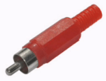
RCA connectors
RCA connectors are used for unbalanced transmission of analog line-level signals, mainly from various recording devices. In addition, this connector is used in the digital interface of the SPDIF format. RCA is the wrong connector to begin with, as the connection of the signal pin of the jack to the signal pin of the jack occurs before the connection of the ground pins. Some companies, one of which is still Neutrik, make RCA plugs with an extended spring-loaded ground contact that connects to the ground contact of the socket before the signal contact. All RCA connectors can be divided into two groups. One is designed to transmit an analog signal, and the other is designed to transmit a digital SPDIF signal, as a result of which they have a characteristic impedance of 75 ohms. The connectors of the first group have terminals for soldering conductors, and the connectors of the second group are crimped. In any case, whatever the connector, its wiring (or crimping) is completely unambiguous: the central contact is signal, and the cylinder around the central contact is common.
Connectors
In terms of design, the EDAC connector is a rectangular-shaped terminal block with two guide pins enclosed in a metal casing. One corner of the casing has an opening with a cable clamp. An interesting feature is that this angle can be rotated. As a result, the cable can come out of the connector either straight or from the side. A fixing screw passes through the casing and the terminal block, which must be tightened when connecting the two parts of the connector. Terminal blocks are available with 12, 20, 38, 56, 90 and 120 contacts. At the same time, the number of contacts in the connector can be any, but, of course, not more than that for which the block is designed. The contacts themselves are gold-plated and are flat plugs. Very reliable multi-pin connector.
D-Sub Connectors
To transmit analog signals in audio equipment, connectors with twenty-five and thirty-seven pins are most often used. At the same time, the former are used mainly for eight-channel symmetrical transmission of line-level audio signals. An example is Tascam's eight-channel DA series digital recorders, which have two connectors, one for eight inputs and one for eight outputs. The D-Sub connector consists of a pin header with two rows of pins (three rows of D-Sub connectors are also used in other areas), with the number of pins in the first row one more than in the second. The contacts are protected by a metal casing, bent in the shape of the letter D. The contact block itself is closed by a plastic or metal casing. The connector is famous for the following: first, compared to many other multi-pin connectors used in audio equipment, it is small. The dimensions facilitate its installation where there is little space, such as on computer sound cards. Secondly, the D-Subminiature connector is notorious for its unreliability. Even with tightly tightened fixing screws, contact may be lost or the casing may fall apart (especially if it is plastic). Thirdly, it is difficult to push a normal eight-pair multicore into the hole in the casing of this connector. Connector contacts are usually gold-plated.
The connector is arranged as follows: a plastic cylindrical contact block with two, four or eight contacts is inserted into a plastic sleeve with a lock. The wire is attached to the contacts with a clamping screw, which requires a hex key. Behind the terminal block, a plastic cable clamp is inserted into the sleeve, after which a plastic union nut is screwed onto it.
Switching, part 4 (practice)
Let's start with the fact that the term "jack" is a misnomer. From English (from which this word was borrowed) "jack" is translated as "nest". Initially, it meant "panel connector" (the cable connector was called "plug"), but now it is increasingly used in the same sense as the word "socket" with us (the counterpart is like "mother"). That is, "jack" is a socket of connectors of any type, whether it be "XLR jack" or "RCA jack". But in Russian, the word "jack" has already become established as the name of a certain type of connector, and it makes no sense to change this. 
 As already mentioned, at the moment there are several types of jack connector. One of these is most often referred to as a "quarter-inch (1/4") jack", but it can also be called a "phone", "A-gauge", or "MI" (short for Musical Instrument). This is perhaps the most common type of connector. - it can be found on almost all types of audio devices.It is used to transmit sound signals from recording and processing devices, musical instruments, timecode signals, various controllers, etc. Although the type name of this connector has the number 1/4 " , which indicates the diameter of the plug, sometimes there are problems of incompatibility of the mating parts: either the plug enters the socket very tightly, or vice versa - the plug hangs in the socket. Problems are caused by a mismatch between the diameters of the plug and socket, but where these inaccuracies in diameters come from is difficult to understand. Probably one of the reasons is that manufacturers use different measurement systems (inch and metric).
  Quarter-inch jacks come in two- and three-pin types. The names of the contacts and the wiring are fully consistent with the above rules. The contacts themselves are made by different companies from different materials. I have seen copper, brass, nickel alloy, silver plated and gold plated contacts.
 TT jack is most often used in patch panels. Its name is an abbreviation for the words Telephone Type, this connector is also called "Bantam" or "Tini". The history of this connector begins at telephone exchanges, where young ladies with pleasant voices sat in headphones in front of huge patch panels, and, having uttered the cherished word "I connect", they stuck jumper cables with TT plugs at the ends into them. At the moment, in most large studios, switching between the mixing console and equipment is most often carried out through patch panels with TT jacks. This is due to the smaller jack diameter, which allows more jacks to fit on the panel (96 TT jacks with label space on a single rack unit versus 48 quarter jack jacks). In addition to being used in patch panels, the TT jack is famous for its old-fashioned pin shape and its generally non-standard diameter of 0.137" or 4.4 mm. There is also the creepy-looking double TT plug that is used in patch panels for RS422 interface connections.
This connector, like TT, is used in patch panels. The TB jack is also called "B-Gauge". In addition, the TB connector is fully compatible with a slightly different pin shape MIL jack, also called "TM", "Long Frame" or "MS" (short for Military Style). With all the variety of names, the diameter of all these connectors is 1/4 "or 6.35 mm. The connectors are two- and three-pin. The names of the contacts and the wiring are fully consistent with the rules for jack-type connectors. The TB jack differs from the quarter-inch only in the shape of the contacts. 
This 3.5mm jack is well known in consumer electronics. In professional equipment, it is most often used to connect headphones, and even then - in small sound modules, portable equipment and other devices where the size of the jack is important. The minijack has become more widespread in multimedia equipment. Most often, three-pin minijacks are used, I saw two-pin ones only once - on the remote control unit from the CD player. The minijack connector is notorious for its unreliability. 
Jack sockets, in addition to the main function - providing mechanical and electrical contact with the mating part, often have the functions of a switch, for which these sockets have additional contacts. For example, United Switch's quarter-inch jack and mini-jack jacks each have nine pins. 

Perhaps the most popular connector manufacturers are Neutrik and Switchcraft. Often there are disputes about whose connectors are better. To begin with, I will try to describe the designs of connectors from both companies - connectors that have become a kind of classic connector building. 
They are also called "Switchcraft", "Cannon" and "canon". In the 60s, ITT Cannon developed a series of connectors for use in Boeing aircraft. The letter "X" identifies the series (before that, ITT Cannon released a series of connectors whose names began with the letter "U"), "L" stands for "Locking" ("fixed"), "R" stands for Rubber ("rubber"). Because previous XLP connectors with plastic insulators had problems oxidizing the silver-plated contacts, the XLR jack used a rubber insulator to clean the contacts when connected. Switchcraft was one of the first to use XLR for audio connections, adding a ground lug to connect to the jacket sleeve, and reverting to a hard plastic insulator. In the 1980s, the use of less oxidized gold-plated pins spread in XLR connectors, and the importance of the rubber insulator decreased. 
 Pin 1 is for common, pin 2 is for positive, and pin 3 is for negative. Pin 0 is the body of the connector, sometimes it is connected to pin 1. This wiring is standard, but sometimes there are devices in which the signal in phase (plus) is transmitted through pin 3 (on such devices they usually write "pin 3 = hot").
This is a combination panel jack from Neutrik for two types of plugs - jack and XLR. It is used as an input connector and saves space on the panel. The jack most often carries line level audio signals in both balanced and unbalanced ways, while XLR is used for balanced mic and line level signals. 
At the moment, there is no consensus on the origin of the name of this connector. However, the most authoritative sources adhere to the version that the name stands for Bayonet Neill-Concelman, where "bayonet" ("bayonet") means the type of connection (bayonets were attached to some rifles in a similar way), and "Neill" and "Concelman" are the names of the inventors of the connector . Although the decoding "British Naval Connector" ("British Naval Connector") is often found. 
They are also called "phono". The Radio Corporation of America (RCA) developed these connectors in the 1930s for the internal connections of radio and TV boxes. These connectors were widely used in turntables to connect a phono cartridge to a preamplifier, because the connectors are inexpensive, work well with the thin shielded cables used for cartridges, and also because the turntables were monophonic and a single-core shielded cable was enough. 
 The name comes from the company EDAC, which produces these connectors, and they are also called ELCO, after another company that also produces connectors of this type. These are multi-pin connectors. They are used to transmit analog signals of line and microphone levels. Outside of patch panels, probably the cheapest device with an EDAC connector is the ADAT tape recorder, where the connector is used to connect eight inputs and eight outputs at the same time. Many cable companies make special 16-channel cables for connecting ADAT tape recorders to a mixing console. These cables have an EDAC connector on one end, and sixteen jack or XLR connectors on the other. However, EDAC is most widely used on large mixing consoles, where all inputs and outputs are made on connectors of this type.
The full name of this multi-pin connector is "D-Subminiature". Most often it can be seen on computers. In audio equipment, it is used to transmit analog signals at mic and line levels, as well as for some audio digital interfaces, such as TDIF. In addition, the D-Subminiature connector is used in various RS interfaces.
This Neutrik invention is used to connect speaker systems. There are three types of connectors: two-pin, four-pin and eight-pin. The most commonly used four-pin connectors. With their help, it is possible to connect broadband and two-way speaker systems. An eight-pin connector is more often used for three- and four-way speaker systems. 

Type.
Contact. 
Type. The type of connector is indicated: (k) - cable, (p) - panel.
Contact. The number of contacts of one connector and the material of the contacts are indicated: (N) - an alloy of nickel and silver, (З) - gold-plated, (С) - silver-plated. 
Switchcraft
A&T Trade
Canare, Neutrik
ISPA
Article rating
08.05.2011
Audio cables- seemingly a fairly simple topic, but once you have a choice, you will quickly find that they vary greatly in purpose, price and quality. This guide will help you understand the different types of cables and connectors.
With all the variety of cable types, they all have similar designs. If we consider the cross section of the cable, then in its center there are one or more wires covered with a layer of insulation. These wires, along with a natural textile lining to strengthen the structure and reduce microphonic effects, are encased in a shielding braid. All this is covered with one or more layers of insulation.
Qualitative characteristics of various audio cables
The wires of cheap cables are most often made of ordinary copper. The wires of more expensive cables are made from oxygen-free copper (Oxygen-Free Copper, OFC), obtained by remelting at a very reduced pressure. Even more expensive are cables, the wires of which are made of silver and gold. Such cables are used where it is necessary to transmit the signal as accurately as possible. In addition, no less expensive carbon wires made of polymeric carbon-containing fiber are used to transmit sound signals. The insulation of most cables is usually made of polyvinyl chloride (PVC), plastisol and polyurethane.
In addition to electrical characteristics, the main of which are resistance, inductance and capacitance, the wire also has important physical characteristics - diameter, cross-sectional area or caliber. Wire diameter is measured in millimeters, cross-sectional area is measured in square millimeters, and there is an American AWG system for gauge ( American Wire Gauge). To match the AWG gauge, diameter, and cross-sectional area of a round wire, there is table .
The main purpose of a cable is to move an electrical signal from one component to another without significantly degrading the signal or introducing noise. There are expensive, excellent quality cables for the true audiophile that are designed and built to keep the signal intact and work without interference. Most musicians don't need this quality when performing, however, it's not an indication and high-fidelity cables won't hurt you. Quality cables will carry better sound, and as you know, if you have better sound, you will sound better.
Other signs of "quality" such as gold-plated connectors and oxygen-free ( oxygen-free) copper wires are not that super important. Gold plating can reduce resistance, but is more prone to wear than nickel plating, so may not be suitable for connectors that are frequently plugged in and out of the mains. Oxygen-free copper wires may offer less resistance, but the width of the wire contributes more to this.
Basically, you need a cable that is flexible, strong, of good quality material with good solder joints. Other features are connectors with a choice of epoxy pots or hot glue (filled with stuffing of one substance or another to prevent movement of the ends of the wires and fix them rigidly) and heat-reducing braids on the ends of the cable (plastic braid around the wires and terminals, which when heated provides a tight fit of the wires and their fixation). Instrument cables must be particularly robust. They constantly move during performance, are often accidentally pulled or stepped on, and plugged in and out of the mains quite often. There are no tool cables that last forever, but there are those that last longer. Another criterion is that it is advisable to buy cables that are long enough, but not too long (because the longer the cable, the greater the likelihood of noise).
Cable Types SOFTWARE FUNCTIONS
Musicians who deal with cables generally fall into four main categories: instrument cables ( instrument cables) , connection cables ( patch cables) , speaker cables ( speaker cables) , and microphone cables ( Microphone cables) . Rule number one: when making a purchase, choose a cable designed for a specific purpose you need. The instrument cable must not be used to connect speakers. It will work, but not properly and, under certain circumstances, may cause problems. And you never want to use a speaker cable as an instrument cable or patch cable, because it's unshielded and extremely susceptible to noise sources.
Instrument cable: As the name suggests, they connect a guitar, bass, keyboard, or other electronic device to an amplifier. It has a positive wire and a shield that serves as a ground. It is designed to transmit low voltage audio signals from the instrument and most often has a 1/4" (6.35 mm) TRS connector, or the so-called "jack" (Eng. jack).
Connection cable: a short cable, used to link various components for circuitry when recording or setting up an amplifier, or to connect effects pedals to each other and automatically connect an instrument to an amplifier. Most often, connecting cables are similar to instrument cables, but they can also be balanced (see below), and can have various types of connectors (XLR, 1/4 "phone, TRS, RCA).
shielded and balanced cable with XLR male connector ( male) at one end and an XLR female connector ( female) with another. Some microphone cables have a TRS mini-jack or USB connector on the end for connecting directly to your computer's sound card or digital recording device. A microphone cable is often used as a long, balanced cable connecting a connected microphone to a mixing console. In addition, a microphone cable is often used for DI communication (DI box) between the amplifier and the mixing console. Microphone cables are also sometimes used for the AES/EBU digital output.
Speaker cable ( speaker cable ): unshielded two-wire cables are much thicker than patch, instrument, or microphone cables. They consist of more wires because they carry a much higher voltage. Even ZIP cord (or tube cord) can be used as speaker cables. They can have 1/4" phone connectors, banana clip(also called MDP connectors), binding post(usually found on stereo amplifiers), or Speakon connectors.
| Multi-channel cables ( Snakes, or "multicore", "multicore cables"): consist of several single cables enclosed in one powerful common insulating sheath. They are used for multi-channel transmission of analog and digital signals, most often over long distances. In addition to single cables, this sheath may contain a plastic or textile cord, which gives the multicores mechanical strength. It is also convenient to tie the end of the multicore to the frame of the patch panel with this cord, for example. Single cables in multicores can be of all three types. Stage "snakes" can contain microphone, connecting and loudspeaker cables and are used for two-way communication between the stage and the sound engineer's remote mixing console. They can have a whole fan of different connectors at one end, and a box at the "stage" end, which is a connector panel with "jacks". There is also a type of studio multicore where the separation of the various cables is necessary to connect the studio equipment. Shielding and insulation of single cables can be either individual, which is good, or common, which is bad due to the impossibility of separating common wires for individual transmission channels. This should be taken into account when buying multi-channel cables, in addition to the main parameters: the length and type of connections. | |
Balanced and Unbalanced Cables (Balanced and Unbalanced)
Line-level interconnect cables come in two types: balanced and unbalanced. Balanced cables are more "quiet" and are often referred to as "professional" cables, while unbalanced cables are referred to as "consumer". Symmetrical are more often used to connect equipment for which noise is unacceptable. An unbalanced cable usually ends with an RCA plug. Balanced cables are easily recognizable by their three-pin XLR connector (or TRS connector). This is dictated by the fact that there are three conductors inside a balanced cable: a signal is transmitted through two of them (positive - positive and negative - negative), and the third is connected to ground. Signals are carried simultaneously in both conductors, and reverse polarity cancels any interference*.
* When two completely identical, but opposite in polarity, signals transmitted on a balanced line enter the signal receiving component - the input of a differential amplifier, the noise induced on the cable is eliminated. This is because the differential stage only amplifies the difference of the two signals. Interference penetrating the line is the same in both conductors, therefore, a differential amplifier will be able to suppress them. This method of eliminating interference that is identical in both conductors of a balanced line is called common-mode rejection. Differential inputs are characterized by their ability to suppress the signal common to both conductors. This parameter is called the common mode rejection ratio (Common-Mode Rejection Ratio, or CMRR). Remember that a balanced line will not make a noisy signal clear. It only prevents additional noise from being transmitted through the interconnect cable. A differential amplifier will only eliminate interference if it is identical in both conductors.
Because balanced cables eliminate any interference and noise, they can be longer than unbalanced cables. Unbalanced cables over 10 inches long are susceptible to noise and require ground reinforcement.
When buying, it is important not to confuse single stereo cables with balanced mono cables. Although they have the same TRS connectors, their purpose and connection are completely different.
Shielding
All cables used in audio equipment, with the exception of speaker cables and optical cables, are shielded to protect the signal from interference that creates noise. This means that a conductive surface (shield) must be placed around the signal wires of the cable to protect the cable wires from electromagnetic radiation. The screen is most often used as a common wire. The purpose is to protect the signal from noise sources such as radio signals, power cords, fluorescent lamps, dimmer rheostats, and some appliances. When you hear the radio through your amplifier, it usually means that the shielding around your amplifier components is not good enough, but don't forget that bad shielding on the cable to your instrument can also be the cause. A good shield can also serve as a ground.
In audio cables, the screen is three types: foil, wire mesh or wire spiral. When manufacturing a screen, cable manufacturers try to ensure that it completely covers the signal wires of the cable. The easiest way to achieve this is to make the screen out of metal (usually aluminum or copper) foil. The signal wires of the cable are wrapped around this foil and a bare wire is laid under it for contact with it. This screen provides 100% coverage of the signal wires. However, the foil screen has disadvantages, the main of which is mechanical unreliability, so it is used in cables intended for stationary use.
Screen mesh braid is the most mechanically robust and flexible form of screen. This is the most common screen type. On stage, mic and instrument cables are constantly bent, pulled, and often stepped on, braided is the best thing you can think of for these conditions. But at the same time, it is difficult to manufacture, and it is difficult to achieve 100% coverage of signal wires with it. Typically, the screen mesh braid covers 60 to 85% of the area of the signal wires. Some firms make very dense mesh braids that cover up to 96% of the wire area in the cable.
The helical wire braid shield has one big advantage - it gives the cable flexibility that is not possible with a foil shield or mesh braid (cable flexibility is more important in live environments). True, this is where all her virtues end. Spiral wire braid covers no more than 80% of the area of the signal wires and, when subjected to physical impacts, quickly becomes unusable (although not as quickly as a foil shield). At the same time, the area covered by it sharply decreases. It is also less resistant to radio frequency (RF) interference because it is actually a coil that has an inductance.
Some companies produce cables with double shielding. Most often, this is a combination of foil with a liquid mesh braid, which serves to strengthen it. They also make a double spiral braid, which is more reliable than a single one, and covers a slightly larger area of \u200b\u200bthe wires.
Types of cable connectors
Typically, six types of cable connectors are used for live sound devices: TRS and XLR for balanced connection and TS, RCA, banana and Speakon- for asymmetrical.
Connectors are divided into sockets (in English they are also called " female", and in Russian -" mom ") and plugs (in English they are also called" male", and in Russian -" dad "). If for jack connectors this division is obvious, then in the case of XLR connectors, for example, the part of the connector with pins is a plug, and the mating part of the connector with holes is a socket.
|
TS phone 1/4"(TS quarter inch jack) - the most common connector for transmitting an audio signal, it can be found on unbalanced connecting cables, instrument and speaker cables. The abbreviation "TS" stands for: T - tip, which means "tip" and S - Sleeve, which can be translated as "sleeve". It is these two parts that this connector consists of. When using a two-pin connector, the contact tip(2) is connected to the signal conductor, and the contact Sleeve(1) - with a common or ground conductor, such as a braided shield. 4 - isolation.
|
TRS phone jack (English) tip,ring,sleeve- which translates as Tip, Ring, Sleeve) looks like TS phone 1/4", with the only exception that it has an additional shaft segment called "ring". "Tip", "ring" and "sleeve" allow you to connect two wires, as well as use the ground. The three-pin connector is soldered when used for symmetrical switching as follows: pin 1 ( Sleeve) is connected to a common conductor. Contact 2 ( tip) is designed to transmit a signal in phase. In this case it is called " hot”, “plus”, “phase”, “phase plus” or “hot”. Pin 3 is designed to transmit a signal in antiphase. He's called " cold”, “minus”, “opposite phase”, “phase minus” or “cold”. In dual channel transmission, pin 1 ( Sleeve) is used to connect to a common conductor, and pins 2 ( tip) and 3 ( ring) - for the signal conductors of the first and second channels, respectively. A special case of two-channel transmission is the transmission of a stereo signal. Headphones are a prime example of this. In stereo transmission, pin 1 ( Sleeve) - common, contact 2 ( tip) carries the left channel signal, and pin 3 ( ring) - right. Another use of two-channel jack connectors is the bidirectional transmission of audio signals. A striking example of this is the gap connector ( insert) channel on the mixing console. As elsewhere, pin 1 is common, but there is no standard wiring for the second and third pins. One of the two remaining contacts is the output, and the second is the input. |
||||
|
XLR connectors(sometimes called " Switchcraft», « Cannon” and “canon”) are what you usually see on the ends of a microphone cable (both female and male connectors). These connectors can have three, four, five or more pins. Three-pin XLR connectors are the most common in audio equipment. They are used for the balanced transmission of analog mic or line level signals, digital signals, and clock signals. Three-pin XLR connectors are used on balanced connecting cables to send the signal from the mixing console to the speakers, and from the DMX controller to the lighting equipment. XLR connectors with more than three pins are used in tube and stereo microphones. |
RCA connectors - most commonly used on consumer stereo equipment, CD players and turntables. RCA cables are usually a pair of wires molded together so that only the ends are separated. Many mixing consoles have RCA inputs for connecting a stereo CD player to PA system, and some consoles also have RCA outputs for connecting to recording devices. |
||||
|
Banana connectors / Banana plug is a reversible connector used on speaker-cables, often only at the end of the amplifier, or at both ends when the amplifiers are provided with an appropriate socket. The main advantage of the banana connector is that the wires are not soldered. The ends of the wires slip into the hole and are held in place with a set screw. This simple design allows you to carry out the necessary repairs on the spot, literally "on the fly". |
Speakon connectors used to connect loudspeakers are increasingly used to connect loudspeakers in PA systems. They are needed here because they are quite reliable and cannot be accidentally pulled out of the socket, which happens with banana plugs or TRS phone jacks. Connectors Speakon designed for high currents, they provide protection against human contact with live parts, which is important for powerful amplifiers. There are three types of connectors: two-pin, four-pin and eight-pin. Most often, four-pin connectors are used. |
||||
|
minijack(1/8" mini jack ) - connector with a diameter of 3.5 mm, widely known for household equipment. In professional equipment, it is most often used to connect headphones, and even then - in small sound modules, portable equipment and other devices where the size of the jack is important. The minijack has become more widespread in multimedia equipment. Connectors can be either TS or TRS. |
Type Connectors D-Sub (multi-pin connector D-Subminiatur e) - more often seen on computers. In audio equipment, it is used to transmit analog signals at mic and line levels, as well as for some audio digital interfaces, such as TDIF. In addition, connector D-Subminiature used in various RS interfaces. D-Sub connectors are 9 -, 15 -, 25 -, 37 and 50-pin. DB25 D-Sub size is commonly used by some audio brands ( Tascam etc.) for analog / digital input / output. Mixers Mackie use DB25 to connect to the interface firewire. DB25 connectors are also used on some multi-channel cables ( multicores) for analogue connections, in particular those using the standard Tascam. |

Adapters
After cables and connectors, adapters are the most common switching devices. As you add equipment, you may find yourself needing a cable with an unusual set of connectors. This is where adapters come in handy.
These devices are designed to connect devices with different types of input and output connectors. Adapters have a small, often cylindrical body, at the ends of which there are connectors of various types. The most common are adapters from XLR to a three-pin quarter-inch jack and from RCA to a two-pin quarter-inch jack. Often there are (mainly for use with headphones) adapters from a three-pin mini-jack to a three-pin quarter-inch jack. There are adapters with other combinations of connectors.
The use of such adapters is possible only if the input and output parameters of the devices match, that is, the inputs and outputs must have the same nominal signal level (for example, linear), transmit the signal in one way (balanced or unbalanced) and match each other in terms of input and output resistances ( impedances). If these conditions are not met, the signal transmission may be of poor quality. So, if the nominal levels of the input and output signals do not match, sound distortion or an increase in the noise level may occur, and if the input and output impedances do not match, signal losses may occur. A classic example of misuse of adapters is connecting an electric guitar with passive pickups with relatively high output impedance (5-25 kΩ) to the line input of a device with an XLR input jack and a relatively low input impedance of 10 kΩ using an XLR-to-jack adapter. There are several errors in such a connection, the main of which is the discrepancy between the input impedance of the device and the output impedance of the guitar (in this case, the input impedance should be much greater than the output, at least ten times). Other special devices are responsible for this, with the help of which such connections can be made. These are matching devices.
Matching devices
These devices are designed to connect devices that for some reason cannot be connected directly using cables and adapters. Reasons for not being able to connect devices directly may be different nominal levels, wrong input and output impedances, different signal transmission methods, or different characteristic impedances. All matching devices can be divided into four groups: level matching devices, impedance matching devices, signal transmission method matching devices, decoupling devices.
In addition, there are devices that use several methods of matching at the same time. Many of these devices provide electrical isolation while performing, for example, impedance conversion or level matching.
Splitters
These devices are designed to split the audio signal in order to distribute it among several receiving devices. Perhaps most often they are used in concert activities, separating the signal for the main and monitor mixers. There are single-channel and multi-channel splitters. Almost all splitters have outputs with transformer isolation, that is, there is no galvanic connection between their outputs and the input. As a result, the influence on each other of devices connected to the outputs of the splitter is eliminated. In addition, there are buttons on the splitters ground/lift, with which it is possible to disconnect the ground contact of the output connector from the common ground of the channel.
The Rolls MS 20, for example, is a single channel mic splitter. The unit has a balanced microphone input on an XLR connector and two transformer-isolated balanced microphone outputs on XLR connectors. In addition to the connectors, there is a Ground/Lift switch that disconnects the ground pins of the output connectors from the input ground.
Switches
 If splitters divide the input signal simultaneously into several outputs, then the switches allow you to send the signal from the input to the selected output, or vice versa - to send the signal from the selected input to the output. They are used to switch the path of the audio signal, when, for example, it is necessary to route the sound from one to another effect processor.
The simplest switch is the so-called A-B Box. It allows you to send a signal from the input to one of the two outputs, or connect one of the two signal sources to one receiver. For example, the A-B Box DOD 270 is capable of sending one output from one of two sources or sending an input signal to one of two receivers. All three connectors (A, B, Com) for connecting sources and receivers are jacks. Switching is carried out by pressing the button-pedal.
Cable testers
If you have PA system, a large sound system that you use regularly for big gigs, then a cable tester is a very small but important investment. Cables can fail or fail periodically, and then it is the cable tester who can quickly tell you where, in what place and what kind of problem it is.
Digital (DIGITAL) cables and connectors
The cables and connectors described above are analog, used for PA systems, instrument connections, and traditional studios. Today, digital technology has added many types of connectors and cables that connect computer serial buses to various external devices such as printers, interfaces, digital recorders and processors, video equipment, and DJ equipment. The variety of different cables, connectors and protocols reflects the constant changes in digital technology. New technologies are often accompanied by new protocols affecting computer hardware, software, and drivers. The following is a description of some of the most commonly used connectors and cables today. One important caveat: often the same type of connector is used for digital signal transmission as for analog ones (XLR and RCA connectors, for example), but cables are usually designed for different impedances and therefore are not interchangeable with similar analog cables.
|
MIDI is an abbreviation that stands for Musical Instrument Digital Interface(musical instrument digital interface). It is a protocol designed to connect electronic instruments to external digital devices. It conveys all aspects of musical performance other than sound - i.e. what note is tuned, how long it lasts, the speed of the beat, etc. - while the actual tone is created by the plug-in sound module. MIDI can also pass control parameters to software and synthesizers, allowing you to actually turn knobs and move sliders using MIDI with remote control support. |
USB is a relatively new type of computer connection that has become the standard for connecting external devices such as printers, cameras, musical instruments, and digital audio devices. USB cables have type A or type B connectors on one end, and a different connector specific to the device being connected on the other side. USB can also serve as a power source for a connected device. Within a few years of its introduction, the specification has been upgraded from the original 1.1 standard to the 2.0 standard as a result, the latter's main difference being that it can transfer data at a faster rate. USB 2.0 is backward compatible with 1.1. The third in a row, a new USB connector - a USB minijack - can often be seen on MP3 players and on some of the company's devices. Roland. |
|
FireWire (IEEE 1394): a protocol pioneered for video because it allows high data rates up to 800 Mbps. It is currently widely used for audio applications. There are three types of FireWire connectors: 4-pin, 6-pin, and 9-pin. The 4 and 6 pin versions are known as FW400. The 9-pin version is known as the FW800. The 6-pin has the same baud rate as the 4-pin but can still supply power. 9-pin can transfer power and is twice as fast as 6 or 4. Adapters are available when you need to link devices that require different connectors. The FW800 is backwards compatible with the other two, but not vice versa. |
S/PDIF- abbreviation for Sony Philips Digital Interface Format. This format for digital audio uses either optical or coaxial cable for transmission. The coaxial version uses RCA plugs, but these cables are not interchangeable with analog RCA, since S/PDIF versions must be 75 ohms. The optical version uses TOSLINK, a standard optical fiber connection system developed by Toshiba. Both versions are capable of carrying two audio streams, typically the left and right channels of a stereo signal. |
|
AES/EBU- format for digital signal transmission, developed by Audio Engineering Society(AES) and European Broadcasting Union(EBU) in the early 1980s. It uses AES Type 1 cable to three conductors, 110 ohm cable and XLR connections. It carries two channels over a single connection and is the transmission protocol on which S/PDIF is based. Due to impedance differences, an XLR mic cable, although it has the same connectors, will not work as an AES/EBU cable. |
BNC-connector is used to connect a thin coaxial cable with a wave impedance of 50 ohms and a diameter of ~0.5 cm. Cables with BNC connectors are used to connect electronic devices (signal generators, oscilloscopes, etc.), as well as to build networks ethernet 10BASE2 standard. This connector type « "bayonet" is often found on cables that carry sync clock signals between digital studio components. They are also found on video equipment and audio testing devices. |
|
Optical cables and connectors: fiber optic technology is often used in digital devices for data transmission. Optical cables allow you to transmit information over longer distances with a higher data transfer rate, according to the principle of light transmission, and do not create any noise at all. Many modern digital devices have two ports, one coaxial and one optical. One of the important optical protocols is ADAT. light pipe. It transmits eight channels of digital audio over a special cable with a specially designed Alesis ADAT connector. |
TDIF (Tascam Digital Interface) is a proprietary format that uses a 25-pin D-Sub cable for transferring eight channels of digital audio between compatible devices. This makes bi-directional communication possible, which means that only one cable needs to be connected to link eight inputs and outputs from one device to another. The old version of TDIF-1 cannot send or receive synchronized information (requires a separate Wordclock connection). The new TDIF-2 protocol can receive and transmit synchronization without additional cables. |
How to distinguish between balanced and unbalanced cables? What is shielding and its benefits. Foil, Wire Mesh, or Wire Helix Screens – Which is Better?
You can divide all line-level interconnect cables into two types - balanced and unbalanced. Balanced cables are most often used in professional applications due to their high noise isolation characteristics.
Unbalanced cables are commonly called household cables, as they are used mainly to connect audio equipment in a particular case. The end of an unbalanced cable usually has an RCA connector.
Unbalanced cables are usually more than 10 inches long, they are very susceptible to any interference, and therefore require additional ground reinforcement. Balanced cables eliminate any noise and interference and can be much longer than unbalanced ones.
You can distinguish balanced from unbalanced cables by the TRS connector or the three-pin XLR connector. A balanced cable consists of three conductors: the first carries a positive signal (positive), the second carries a negative signal (negative), and the third is used as ground.
In both conductors, the signals go simultaneously, the reverse polarity prevents any interference. It is important to distinguish single stereo cables from balanced mono cables. Despite the fact that they have similar TRS connectors, the connection method, as well as their purpose, are completely different.
When connecting audio equipment, use only shielded cables. The only exceptions are optical cables and cables for loudspeakers. Shielding is the creation of a kind of protective wall that protects the cable wires, and hence the signal passing through them, from electromagnetic radiation.
If, in addition to the main signal, extraneous sounds break through the cable, this means that the protection is ineffective and shielding must be strengthened. In addition, a good screen can serve as a ground.
In audio cables, shields come in three varieties - from a wire spiral or mesh and from foil. High-quality cable shielding is possible only when the shield completely covers the wires through which the signal passes.
If the screen is made of aluminum or copper foil, the signal wires of the cable and a bare wire are placed under it, which is then carefully wrapped. In this design, shielding is achieved almost one hundred percent.
The disadvantages of foil screens are that they are subject to mechanical wear. For longer operation of cables with such shielding, they are used to connect stationary equipment.
The wire mesh screen is by far the most flexible and reliable. The braiding of cables with a mesh allows you to transfer mechanical stress with minimal losses. This type of screen is more in demand.
For professional purposes, such as stage work, where the cables are constantly exposed to mechanical stress, wire mesh shielding is the best option.
The disadvantage of such a screen is the complexity in manufacturing, besides, it is almost impossible to cover 100 percent of the signal wires with it. Standard screen wire mesh can cover 60 to 85% of all wires. Sufficiently dense wire braids are made by only a small number of manufacturers, and the protection index in this case does not exceed 96% of the wire coverage area.
The third shielding option is a spiral wire shield. The advantage of such protection is that it allows the cable to bend in a way that cables with the first two shielding options cannot. It is this quality that is most appreciated in concert activity.
Disadvantages - the fragility of the work, since under mechanical action the screen quickly becomes unusable. In addition, cable protection coverage reaches only 80%.
In addition, the screen created in this way is the most sensitive to radio frequency interference. And all due to the fact that the wire spiral itself, like a coil, has inductance.
There are audio cables today with a double form of shielding. Basically, it is a combination of wire mesh and foil that maintains the strength of the braid. There is also a double spiral braid, it not only covers most of the wires, but is also much more reliable than a single one.