Symbols for the floor plan of the building. science engineering technology
Some clients who decide to become owners of apartments in a modern new building (not yet commissioned or unfinished house) often have difficulty reading the layout of their own apartment or house in its entirety.
I will try to present some concepts and tips, the knowledge of which will make the "interpretation" of the layouts a simple and unconstrained affair.
So. You are in the office of a construction company or in the sales department of a new building, or maybe even better - you went to the official website of the sales department. Before you are the layouts (typical floor plan) of the house in which you want to buy an apartment (see "Fig. 1", as an example, the 5th floor plan is chosen)
Rice. 1 Determination of the position of the apartment
Let's start with the "apartment" risers *. The countdown of the risers starts from the elevator from left to right. Such a "coordinate system" is used by real estate specialists, with the help of which it is possible to accurately describe the position of the apartment on the layout, its orientation in space, etc.
Thus, we have determined where your apartment is located, where its windows face (courtyard or facade), whether it is internal or corner, and where it is located in relation to the elevator. For example, let's take a one-room apartment in the 2nd riser. 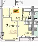
Fig.2 One-room apartment
Please note that the apartment layout always shows the total area. IN this case it is 32.58 sq.m. Sometimes the square that contains this data, in addition to the number of rooms, has three fields that display either the total / living and kitchen area, or the total / heated (total loggia with a coefficient) and living area. For example:
Fig. 3 Designation of the area of the apartment
The total area of the apartment is 34.04 sq.m., heated 34.04-1.92 = 32.12 sq.m. And residential 15.11 sq.m. (i.e. the area of the room or the sum of the areas, if we are talking about 2 or more rooms)
In the case in Fig. 2 is the common and living area. I want to draw your attention to the loggia, or rather the calculation of the area, which is included in the total area of the apartment. Majority construction companies consider it with a coefficient of 0.5 (Fig. 3), i.e., the area of \u200b\u200bthe loggia for which you pay is determined as 3.84 * 0.5 \u003d 1.92 sq.m. But there are companies that consider loggias 1/1 or with a coefficient of 0.3.
You can also view the layout from left to right.
Now floor plan
Fig.2. Upon entering the apartment, we find ourselves in a hall/entrance hall of 5.79 sq.m. Bathroom 3.96 joint. Kitchen 7.88 sq.m. with access to the loggia 1.79 sq.m. Room 11.71 sq.m. and dressing room 2.34 sq.m.
Fig.3. Upon entering the apartment, we find ourselves in a hall-entrance hall of 3.68 sq.m. Room 15.11 sq.m. with access to the loggia 3.84 sq.m. Kitchen 9.51 sq.m. with the possibility of access to the same loggia. Bathroom 3.82 joint.
The layout of the apartment also reflects very important information about which walls are load-bearing and which are not. In the diagram, load-bearing walls and columns are highlighted either in color or in thickness.
GOST 21.201-2011
Group J01
INTERSTATE STANDARD
System project documentation for construction
CONDITIONAL GRAPHIC IMAGES OF ELEMENTS OF BUILDINGS, STRUCTURES AND STRUCTURES
System of design documents for construction. Symbol graphics elements of buildings, works and structures
ISS 01.100.30
Introduction date 2013-05-01
Foreword
The goals, basic principles and basic procedure for carrying out work on interstate standardization are established by GOST 1.0-92 "Interstate standardization system. Basic provisions" and GOST 1.2-2009 "Interstate standardization system. Interstate standards, rules and recommendations for interstate standardization. Rules for the development, adoption, application, renewal and cancellation
About the standard
1 DESIGNED BY OPEN joint stock company"Center for the Methodology of Rationing and Standardization in Construction" (JSC "CNS")
2 INTRODUCED by the Technical Committee TC 465 "Construction" Russian Federation
3 ADOPTED by the Interstate Scientific and Technical Commission for Standardization, Technical Regulation and Conformity Assessment in Construction (MNTKS) (Minutes of December 8, 2011 N 39)
Voted to accept:
Short name of the country according to MK (ISO 3166) 004-97 | Abbreviated name of the body government controlled construction |
|
Azerbaijan | Gosstroy |
|
Ministry of Urban Development |
||
Kazakhstan | Agency for Construction and Housing and Communal Services |
|
Kyrgyzstan | Gosstroy |
|
Ministry of Construction and regional development |
||
the Russian Federation | Department of Architecture, Construction and Urban Planning Policy of the Ministry of Regional Development |
|
Tajikistan | Agency for Construction and Architecture under the Government |
|
Uzbekistan | Gosarchitektstroy |
|
Ministry of Regional Development, Construction and Housing and Public Utilities |
4 By order of the Federal Agency for Technical Regulation and Metrology of October 11, 2012 N 481-st, the interstate standard GOST 21.201-2011 was put into effect as the national standard of the Russian Federation from May 1, 2013.
5 INSTEAD OF GOST 21.501-93 in part of Appendix 1 and ST SEV 1633-79, ST SEV 2825-80, ST SEV 2826-80, ST SEV 4937-84
Information on the entry into force (termination) of this standard is published in the monthly information index " National Standards".
Information about changes to this standard is published in the annually published information index "National Standards", and the text of changes and amendments - in the monthly published information index "National Standards". In case of revision or cancellation of this standard, the relevant information will be published in the monthly published information index "National Standards"
1 area of use
1 area of use
This standard establishes the main conditional graphic images and designations of elements of buildings, structures and building structures used in the design and working documentation for construction.
2 Normative references
This standard uses references to the following standards:
GOST 2.303-68 one system design documentation. lines
GOST 2.306-68 Unified system for design documentation. Designations of graphic materials and the rules for their application on the drawings
GOST 2.315-68 Unified system for design documentation. Images of simplified and conditional fasteners
GOST 21.112-87 Design documentation system for construction. Handling equipment. Conventions
GOST 21.204-93 Design documentation system for construction. Conditional graphic symbols and images of elements master plans and transport facilities
GOST 21.205-93 Design documentation system for construction. Symbols of elements of sanitary systems
GOST 21.206-93 Design documentation system for construction. Symbols of pipelines
GOST 21.302-96 Design documentation system for construction. Symbols in the documentation for engineering and geological surveys
GOST 21.501-2011 System of project documentation for construction. Rules for the implementation of working documentation for architectural and structural solutions
Note - When using this standard, it is advisable to check the validity of reference standards in the territory of the state according to the corresponding index of standards compiled as of January 1 of the current year, and according to the corresponding information indexes published in the current year. If the reference standard is replaced (modified), then when using this standard, you should be guided by the replacing (modified) standard. If the referenced standard is canceled without replacement, the provision in which the reference to it is given applies to the extent that this reference is not affected.
3 General
3.1 The designed buildings, structures and their elements are depicted on the drawings using conventional graphic symbols and simplified images established by this standard, taking into account the requirements of GOST 21.501, as well as using symbols established by GOST 2.306, GOST 21.112, GOST 21.204, GOST 21.205, GOST 21.206 and GOST 21.302.
3.2 The types of lines used in the execution of conditional images and symbols must comply with GOST 2.303.
3.3 It is allowed to use additional symbols and symbols that are not provided for in this standard, explaining them on the drawing or in the general data on working drawings.
4 Conditional graphic images and symbols
4.1 Walls
Walls and partitions (without filling openings) in the drawings are depicted in accordance with table 1.
Table 1
Name | Image |
1 Wall with opening without parapet and lintel | |
2 Wall with opening and lintel | |
3 Wall with opening, parapet and lintel | |
4 Wall with opening, vaulted lintel, quarter window and thin wall parapet | |
5 Wall with openings located one above the other | |
6 Wall with an opening located at the bottom (parapet zone) | |
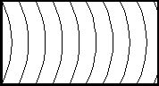
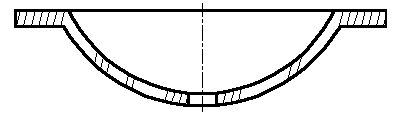
7 Horizontally shaped wall (curved and rounded) | |
8 Wall with variable thickness in vertical section | |
9 An inclined wall with a section thickened at the bottom | |
10 Variable thickness wall with opening and parapet* | |
11 Sloping wall with opening and parapet** | |
12 Vertical wall with decoration | |
13 Partition of glass blocks (on the plan and section) | |
* The opening is not shown in the plan. ** In the plan, the invisible face of the wall is not shown and the opening is depicted in a simplified form. NOTE Thin walls (less than 2 mm on the appropriate scale) are drawn in black. The limitations of the openings in this case are depicted with short transverse strokes. |
|
4.2 Supports and columns
Supports, columns and pylons are depicted in accordance with table 2.
table 2
Name | Image |
|
on the cut |
||
1 Column (support) | ||
2 Column with haunches and a purlin (crossbar) | ||
3 Column with a section that increases or decreases upwards | ||
4 Composite column | ||
5 Support (pylon) with a section that increases or decreases upwards | ||
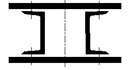
6 Metal column: | ||
solid wall | ||
Two-branch | ||
Note - Image a - for columns without a console, b and c - for columns with a console. | ||
Notes 1 The horizontal plane of the section of columns, supports and pylons is placed at a height of 1 m above the floor. If the base of the column is made according to a special design, then the horizontal plane of the section is located in the lower part of the column above the base. Design features of the capital of the column (for example, haunches) are depicted with a thin dashed line. 2 In the case of a variable section of the columns, the horizontal plane of the section is performed in the lower part of the support. |
||
4.3 Trusses, slabs and ties
Trusses, slabs and connections are depicted in accordance with table 3.
Table 3
Name | Image |
|
on the cut |
||
Note - Image a - for a reinforced concrete truss, b - for a metal truss. | ||
2 Plate, panel ribbed | ||
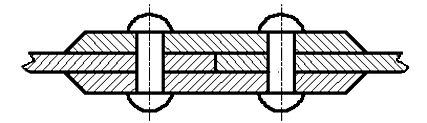
3 Metal connection: | ||
a) single plane: | ||
vertical | ||
Horizontal | ||
b) two-plane | ||
c) strands | ||
4.4 Openings and openings
Openings and holes are depicted in accordance with table 4.
Table 4
Name | Image |
1 Opening or opening in a wall, ceiling, partition, roof (designed without filling). Note - It is allowed not to draw a broken line inside the image if it is unequivocally clear that this is an opening or a hole. | |
2 Opening or hole to be punched in an existing wall, partition, roof, floor | |
3 Opening or opening in an existing wall, partition, floor, ceiling to be sealed. Note - In the explanatory inscription, instead of the ellipsis, the material of the bookmark is indicated. | |
4 Window opening (on the plan and section): | |
a) no quarter | |
b) with a quarter. Note - For drawings on a scale of 1:200 and smaller, as well as for drawings of prefabricated structures, openings are depicted in a simplified form (without quarters). |
4.5 Niches, grooves and furrows
4.5.1 Niches, grooves and grooves of walls and floors are depicted in accordance with table 5.
4.5.2 If the imaginary plane of the section passes outside the image of niches, grooves and furrows, then their contours on the plan and section are depicted with a thin dashed line.
Table 5
Name | Image |
1 Niche, groove (in the cut plane) Note - It is allowed not to draw a diagonal inside the image, if it is unequivocally clear that this is a groove or a niche. | |
2 Groove in the floor (in the plane of the cut) Note - The dimensions of the grooves and niches on the leader line shelf are indicated in the following sequence: width, height and depth. For niches and grooves of circular cross section indicate the dimensions of the diameter and depth. | |
3 Groove in floor (above cut plane) | |
4 Furrow Notes 1 Furrows are depicted on a scale of 1:100 and 1:50 and larger and are not depicted on a scale of 1:200 and smaller. 2 The dimensions of the furrows on the shelf of the leader line are indicated in the following sequence: width, depth, length. |
4.6 Ramps, stairs and blind areas
Ramps, stairs and blind areas are depicted in accordance with table 6.
Table 6
Name | Image |
|
on the cut |
||
Notes 1 The slope of the ramp is indicated on the plan as a percentage (for example, 10.5%) or as a ratio of height and length (for example, 1:7). 2 The arrow on the plan indicates the direction of the rise of the ramp. | ||
2 stairs: | 1:50 scale and larger |
|
a) lower march | ||
b) intermediate marches | On a scale of 1:100 and smaller, as well as for layouts of elements of prefabricated structures |
|
c) upper march | ||
3 Metal ladder: | ||
a) vertical | ||
b) oblique | ||
4 blind area | ||
Note - On the plans of the stairs, the arrow indicates the direction of the rise of the march. |
||
4.7 Doors and gates
Doors and gates on the plan are depicted in accordance with table 7.
Table 7
Name | Image |
1 Door (gate) single leaf | |
2 Door (gate) double leaf | |
3 Door double single leaf | |
4 Double double door | |
5 Single door with swing leaf (right or left) | |
6 Double-leaf door with swinging leaves | |
7 Door (gate) sliding single-leaf external | |
8 Door (gate) retractable single leaf opening into a niche | |
9 Door (gate) sliding two-leaf | |
10 Door (gate) lifting | |
11 Door (gate) folded | |
12 Door (gate) folded-sliding | |
13 revolving door | |
14 Overhead gates | |
Notes 1 In the drawings of scales 1:50 and larger, doors (gates) are depicted with thresholds, quarters, etc. 2 Variants of conditional images of doors, marked with the letter "b", are allowed. |
|
4.8 Window sashes
Window frames on the facade are depicted in accordance with table 8.
Table 8
Name | Image |
1 Side hanging binding, inward opening | |
2 Side hanging binding, outward opening | |
3 Bottom-hung binding, inward-opening | |
4 Bottom-hung binding, outward opening | |
5 Top-hung binding, inward-opening | |
6 Top-hung binding, outward opening | |
7 Binding with medium hanging horizontal | |
8 Binding with medium vertical hanging | |
9 Sliding binding | |
10 Lift binding | |
11 Binding deaf | |
12 Side-hung or bottom-hung binding, inward-opening. Note - The top of the sign is directed to the strapping, on which the binding is not hung. |
4.9 Reinforcing products
Reinforcing products are depicted in accordance with table 9.
Table 9
Name | Image |
|
1 Conventional fittings | ||
1.1 Reinforcing bar: | ||
a) main view | ||
b) section | ||
1.2 Reinforcing bundle with a marking indicating the number of rods in the bundle: | ||
a) main view | ||
b) section | ||
1.3 Straight bars stacked on top of each other in a plan or view, with corresponding bar ends marked as thin lines | ||
1.4 Reinforcing bar end with anchorage: | ||
a) with a hook (bent at an angle of 180°) | ||
b) with a bend at an angle of 90° to 180° | ||
c) with a bend at an angle of 90 ° | ||
1.5 Anchor ring or plate: | ||
a) main view | ||
b) end view | ||
1.6 Reinforcing bar with a right-angled bend extending away from the reader | ||
1.7 Reinforcing bar with a right angle bend away from the reader in documentation intended for microfilming and where the bars are very close to each other | ||
1.8 Reinforcing bar with a right angle bend towards the reader | ||
2 Rebar connections |
||
2.1 Connecting rods with a mechanical coupling: | ||
a) extension sleeve | ||
b) compression clutch | ||
2.2 One flat frame or mesh: | ||
a) simplified (transverse rods are applied at the ends of the frame or in places where the pitch of the rods changes) | ||
"Unified system of design documentation. Designations of graphic materials and rules for their application on drawings"
(approved by a resolution of the Committee of Standards, Measures and Measuring Instruments under the Council of Ministers of the USSR in December 1967)
Unified system for design documentation.
Graphical designs of materials and rules for their representation.
Introduction date 1 January 1971
Instead of GOST 3455-59 and GOST 11633-65
1.
This standard establishes the graphic designations of materials in sections and on facades, as well as the rules for applying them to the drawings of all industries and construction.
1a. The general graphic designation of materials in sections, regardless of the type of materials, must correspond to the drawing:
2.
Graphic designations of materials in sections, depending on the type of materials, must correspond to those given in Table 1.
It is allowed to use additional designations of materials not provided for in this standard, explaining them in the drawing.
Table 1.
| A.1 Metals and hard alloys | |
| Clause 2 Non-metallic materials, including fibrous monolithic and slab (pressed), except for those specified below |
 |
| A.3 Wood |
 |
| P.4 Natural stone |
 |
| P.5 Ceramics and silicate masonry materials |
 |
| P.6 Concrete |
 |
| A.7 Glass and other translucent materials |
 |
| A.8 Liquids |
 |
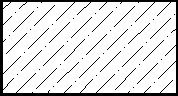
| A.9 Natural soil |
 |
Notes:
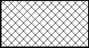
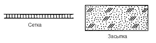
3. Establish the following designations of the mesh and backfill of any material (in section), indicated in the figure:
4. When highlighting materials and products on the view (facade), their graphic designations must correspond to those indicated in table 2.
Table 2.
Notes:
![]()
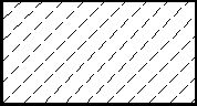
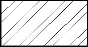
Drawing 2a. Inclined parallel lines of hatching to the line of the contour of the image
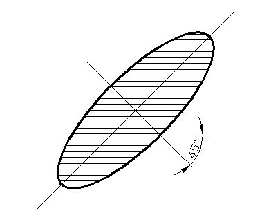
Drawing 2b. Inclined parallel lines of hatching to the axis of the image contour
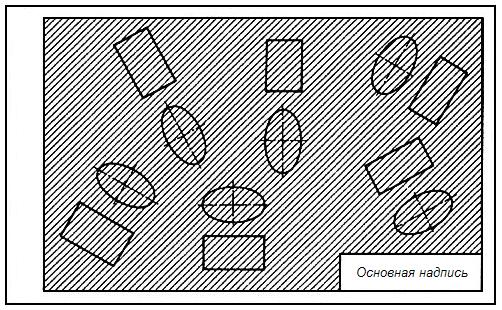
Drawing 2. Inclined parallel lines of hatching to the lines of the drawing frame
If the hatch lines, reduced to the lines of the drawing frame at an angle of 45 °, coincide in direction with the lines of the contour or center lines, then instead of an angle of 45 °, an angle of 30 ° or 60 ° should be taken (drawings 3 and 4). 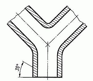
Drawing 3. Coincidence of hatch lines in the direction with contour lines or center lines

Drawing 4. Coincidence of hatch lines in the direction with contour lines or axial lines
Hatching lines should be applied with an inclination to the left or right, but as a rule, in the same direction on all sections related to the same part, regardless of the number of sheets on which these sections are located.
6.
The distance between parallel straight hatching lines (frequency) should, as a rule, be the same for all sections of a given part performed on the same scale and is selected depending on the hatching area and the need to diversify the hatching of adjacent sections. The specified distance should be from 1 to 10 mm, depending on the hatching area and the need to diversify the hatching of adjacent sections.
7.
Narrow and long cross-sectional areas (for example, stamped, rolled and other similar parts), the width of which in the drawing is from 2 to 4 mm, it is recommended to hatch completely only at the ends and at the contours of the holes, and the rest of the cross-sectional area - in small areas in several places (drawings 5 and 6). In these cases, glass hatching lines (drawing 7) should be applied with an inclination of 15 - 20 ° to the line of the larger side of the section contour.
Drawing 5. Hatching of narrow and long cross-sectional areas
Hatching of all designations in this case is done by hand. 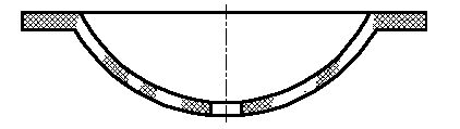
Drawing 6. Hatching of narrow and long cross-sectional areas
Drawing 7. Glass hatching lines
8.
Narrow cross-sectional areas, the width of which in the drawing is less than 2 mm, may be shown in black, leaving gaps between adjacent sections of at least 0.8 mm (drawings 8, 9).
In construction drawings, it is allowed to designate any material as metal on sections of a small area or not to use the designation at all, making an explanatory inscription in the field of the drawing. 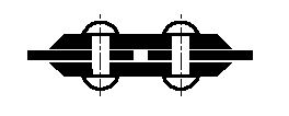
Drawing 8.
Drawing 9.
9.
The designation specified in clause 3, Table 1, and the designation of the backfill in the section are performed by hand.
10.
For adjacent sections of two parts, you should take the slope of the hatching lines for one section to the right, for the other - to the left (opposite hatching).
When hatching "in a cage" for adjacent sections of two parts, the distance between the lines of hatching in each section must be different.
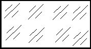
In adjacent sections with hatching of the same slope and direction, you should change the distance between the hatching lines (drawing 10) or shift these lines in one section relative to another without changing their angle of inclination (drawing 11). 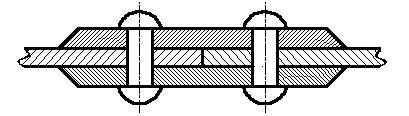
Drawing 10. Adjacent sections with hatching of the same slope and direction with a changed distance between the hatching lines.
Drawing 11. Adjacent sections with hatching of the same slope and direction with a shift of these lines in one section relative to another without changing their angle of inclination.
11.
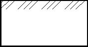
At large areas sections, as well as when specifying the soil profile, it is allowed to apply the designation only at the section contour with a narrow strip of uniform width (drawing 12). 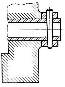
Drawing 12. Designation for large cross-sectional areas.