Voltage converter circuit 12 220 5000W. High voltage and more. How to choose a car voltage converter
A home-made voltage converter (inverter) 12 volts to 220 volts can be useful for motorists driving their car to nature, fishing, and cottages. It allows you to charge your phone, connect lamps for lighting at night, work and play on a laptop, watch TV.A 12 volt to 220 volt converter with a maximum output power of 500 W is assembled on 2 domestic microcircuits (K155LA3 and K155TM2) and 6 transistors, and several radio components. To increase efficiency and prevent strong heating, very powerful IRLR2905 field-effect transistors with minimal resistance are used in the output stage of the device. It is possible to replace it with IRF2804, but the converter power will drop a little
On the elements DD1.1 - DD1.3, C1, R1, according to the standard scheme, a master generator of rectangular pulses with an approximate frequency of 200 hertz is assembled. From the output of the generator, the pulses follow a frequency divider, consisting of elements DD2.1 - DD2.2. As a result, at the output of the divider (pin 6 of the DD2.1 element), the pulse repetition rate is reduced to 100 hertz, and already at the output of 8 DD2.2. the signal frequency is 50 hertz.
A rectangular signal from pin 8 of the DD1 chip and from pin 6 of the DD2 chip is fed to the diodes VD1 and VD2, respectively. In order for the field-effect transistors to open completely, it is necessary to increase the amplitude of the signal that comes from the diode VD1 and VD2; for this, transistors VT1 and VT2 are used. With the help of transistors VT3 and VT4 (they act as a driver), the output power transistors are controlled. If no errors were made during the assembly of the inverter, then it starts working immediately after switching on. It is possible that it may be necessary to select the resistance of the resistor R1 so that the output is exactly 50 hertz.
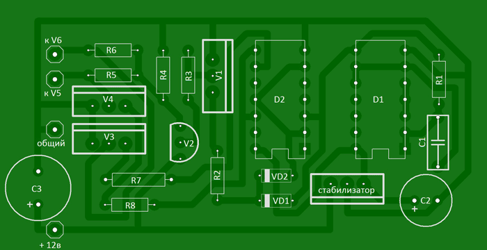
Voltage converter (inverter) 12 / 220 50 Hz 500 W DIY circuit
Silicon transistors VT1, VT3 and VT4 - KT315 with any letter. Transistor VT2 can be replaced by KT361. Stabilizer DA1 is a domestic analogue of KR142EN5A. All resistors in the circuit are 0.25W. Diodes any KD105, 1N4002. Capacitor C1 with a stable capacity - type K10-17. As a transformer TP1, it is possible to use a power transformer from an old Soviet TV. All windings must be removed, leaving only the mains winding. Over the network winding, simultaneously wind two windings with a PEL wire - 2.2 mm. Field power transistors must be installed on an aluminum finned radiator with a total area of 750 sq.cm.It is recommended to start the converter (inverter) for the first time through a household incandescent lamp of 220 volts and a power of 100 - 150 watts, by connecting it in series to one of the supply wires, this will protect you from damage to radio components in case of a mistake.
When working with step-up converters or inverters, follow the rules of electrical safety, as work is done with a voltage that is dangerous for the body !!! The output secondary winding during adjustment and assembly must be insulated with cambric rubber tubing to avoid accidental contact.
I propose a circuit for a voltage converter (inverter) 12 / 220V (power up to 500 watts), powered by a 12V battery, which can be useful in a car and at home for lighting, to power a TV, a small refrigerator, etc. The circuit is assembled on two microcircuits of the 155th series and six transistors. The output stage uses field-effect transistors with a very low on-resistance, which increases the efficiency of the converter and eliminates the need to install them on radiators that are too large.

Let's deal with the operation of the circuit: (see diagram and diagram). On the D1 chip, a rectangular pulse generator is assembled, the repetition rate of which is about 200 Hz - diagram "A". From pin 8 of the microcircuit, the pulses are fed further to the frequency dividers assembled on the elements D2.1 - D2.2 of the D2 microcircuit. As a result, at pin 6 of the D2 chip, the pulse repetition rate becomes half as much - 100 Hz - diagram "B", and at pin 8 the pulses become equal to a frequency of 50 Hz - diagram "C". Non-inverted pulses of 50 Hz are taken from pin 9 - diagram "D". On the diodes VD1-VD2, an "OR" logic circuit is assembled. As a result, the pulses taken from the pins of the microcircuits D1 pin 8, D2 pin 6 form a pulse corresponding to the "E" diagram on the cathodes of the diodes. The cascade on transistors V1 and V2 serves to increase the amplitude of the pulses necessary for the full opening of the field-effect transistors. Transistors V3 and V4, connected to outputs 8 and 9 of the D2 chip, open in turn, thereby blocking one field-effect transistor V5, then another V6. As a result, the control pulses are formed in such a way that there is a pause between them, which eliminates the possibility of through current flowing through the output transistors and significantly increases the efficiency. Diagrams "F" and "G" show the generated control pulses of transistors V5 and V6.
A correctly assembled converter starts working immediately after power is applied. When setting up, you should connect a frequency meter to the output of the device and set the frequency to 50-60 Hz by selecting resistor R1, and, if necessary, capacitor C1.
About details
Transistors KT315 with any letter index, KT209 can be replaced with KT361 with any letter index. We will replace the voltage stabilizer KA7805 with the domestic KR142EN5A. Any resistors with a power of 0.125 ... 0.25 watts. Almost any low-frequency diodes, for example, KD105, IN4002. Capacitor C1 type K73-11, K10-17V with low capacitance loss during heating. The transformer is taken from an old black-and-white tube TV, for example: "Spring", "Record". The winding for a voltage of 220 volts remains, and the remaining windings are removed. Over this winding, two windings are wound with PEL wire - 2.1 mm. For better symmetry, they should be wound simultaneously in two wires. When connecting the windings, phasing should be taken into account. Field-effect transistors are fixed through mica gaskets to a common aluminum radiator with a surface area of at least 600 sq.cm.

List of radio elements
| Designation | Type | Denomination | Quantity | Note | Shop | My notepad |
|---|---|---|---|---|---|---|
| Linear Regulator | UA7805 | 1 | KR142EN5A | To notepad | ||
| D1 | Valve | K155LA3 | 1 | To notepad | ||
| D2 | D flip-flop | K155TM2 | 1 | To notepad | ||
| V1, V3, V4 | bipolar transistor | KT315B | 3 | To notepad | ||
| V2 | bipolar transistor | KT209A | 1 | KT361 | To notepad | |
| V5, V6 | MOSFET transistor | IRLR2905 | 2 | Through mica pads | To notepad | |
| VD1, VD2 | Diode | KD522A | 2 | KD105, 1N4002, etc. | To notepad | |
| C1 | Capacitor | 2.2uF | 1 | K73-11, K10-17V | To notepad | |
| C2 | 470uF | 1 | To notepad | |||
| C3 | electrolytic capacitor | 2200uF | 1 | To notepad | ||
| R1 | Resistor | 680 ohm | 1 | To notepad | ||
| R2 | Resistor | 7.5 kOhm | 1 | To notepad | ||
| R3, R5-R8 | Resistor |
A car voltage inverter can sometimes be incredibly useful, but most products in stores either sin in quality or are not satisfied with their power, but are not cheap at the same time. But after all, the inverter circuit consists of the simplest parts, therefore we offer instructions for assembling a voltage converter with our own hands.
Enclosure for inverter
The first thing to consider is the electricity conversion loss generated as heat on the circuit switches. On average, this value is 2-5% of the rated power of the device, but this indicator tends to grow due to improper selection or aging of components.
Heat removal from semiconductor elements is of key importance: transistors are very sensitive to overheating and this is expressed in the rapid degradation of the latter and, probably, their complete failure. For this reason, the base for the case should be a heat sink - an aluminum radiator.

Of the radiator profiles, an ordinary “comb” with a width of 80-120 mm and a length of about 300-400 mm is well suited. screens of field-effect transistors are attached to the flat part of the profile with screws - metal patches on their rear surface. But even with this, not everything is simple: there should be no electrical contact between the screens of all transistors of the circuit, therefore the radiator and fasteners are insulated with mica films and cardboard washers, while a thermal interface is applied on both sides of the dielectric gasket with a metal-containing paste.

We determine the load and purchase components
It is extremely important to understand why an inverter is not just a voltage transformer, and also why there is such a diverse list of such devices. First of all, remember that by connecting the transformer to a DC source, you will not get anything at the output: the current in the battery does not change polarity, respectively, the phenomenon of electromagnetic induction in the transformer is absent as such.
The first part of the inverter circuit is an input multivibrator that simulates network oscillations to complete the transformation. It is usually assembled on two bipolar transistors capable of swinging power switches (for example, IRFZ44, IRF1010NPBF or more powerful - IRF1404ZPBF), for which the most important parameter is the maximum allowable current. It can reach several hundred amps, but in general, you just need to multiply the current value by the battery voltage to get an approximate number of watts of power output without taking into account losses.
 A simple converter based on a multivibrator and power field switches IRFZ44
The frequency of the multivibrator is not constant, it is a waste of time to calculate and stabilize it. Instead, the current at the output of the transformer is converted back to DC by a diode bridge. Such an inverter can be suitable for powering purely active loads - incandescent lamps or electric heaters, stoves.
On the basis of the obtained base, other circuits can be assembled that differ in the frequency and purity of the output signal. It is easier to make the selection of components for the high-voltage part of the circuit: the currents here are not so high, in some cases the assembly of the output multivibrator and filter can be replaced with a pair of microcircuits with the appropriate binding. Capacitors for the load circuit should be electrolytic, and for circuits with a low signal level, mica.
 A variant of the converter with a frequency generator on K561TM2 microcircuits in the primary circuit
It is also worth noting that in order to increase the final power, it is not at all necessary to purchase more powerful and heat-resistant components of the primary multivibrator. The problem can be solved by increasing the number of converter circuits connected in parallel, but each of them will require its own transformer.
 Option with parallel connection of circuits
The struggle for a sinusoid - we analyze typical circuits
Voltage inverters are used everywhere today, both by car enthusiasts who want to use household appliances away from home, and by residents of autonomous dwellings powered by solar energy. And in general, we can say that the width of the spectrum of current collectors that can be connected to it directly depends on the complexity of the converter device.
Unfortunately, a pure "sine" is present only in the main power supply, it is very, very difficult to achieve the conversion of direct current into it. But in most cases this is not required. To connect electric motors (from a drill to a coffee grinder), a pulsating current with a frequency of 50 to 100 hertz is sufficient without smoothing.

ESL, LED lamps and all kinds of current generators (power supplies, chargers) are more critical to the choice of frequency, since their operation scheme is based on 50 Hz. In such cases, microcircuits called a pulse generator should be included in the secondary vibrator. They can switch a small load directly, or act as a “conductor” for a series of power switches in the inverter output circuit.
But even such a cunning plan will not work if you plan to use an inverter for stable power supply to networks with a mass of heterogeneous consumers, including asynchronous electrical machines. Here, a pure "sine" is very important and only frequency converters with digital signal control can realize this.
Transformer: pick up or do it yourself
To assemble the inverter, we lack only one circuit element that performs the transformation of low voltage into high. You can use transformers from personal computer power supplies and old UPSs, their windings are just designed to transform 12/24-250 V and vice versa, it remains only to correctly determine the conclusions.

And yet it is better to wind the transformer with your own hands, since ferrite rings make it possible to do it yourself and with any parameters. Ferrite has excellent electromagnetic conductivity, which means that transformation losses will be minimal even if the wire is wound by hand and not tightly. In addition, you can easily calculate the required number of turns and wire thickness using calculators available on the network.

Before winding, the core ring must be prepared - remove the sharp edges with a needle file and wrap it tightly with an insulator - fiberglass impregnated with epoxy glue. This is followed by the winding of the primary winding from a thick copper wire of the calculated section. After dialing the required number of turns, they must be evenly distributed over the surface of the ring with an equal interval. The winding leads are connected according to the diagram and insulated with heat shrink.

The primary winding is covered with two layers of lavsan electrical tape, then a high-voltage secondary winding and another layer of insulation are wound. An important point - you need to wind the "secondary" in the opposite direction, otherwise the transformer will not work. Finally, a semiconductor thermal fuse must be soldered to one of the taps, the current and operating temperature of which are determined by the parameters of the secondary winding wire (the fuse case must be tightly wound to the transformer). From above, the transformer is wrapped with two layers of vinyl insulation without an adhesive base, the end is fixed with a screed or cyanoacrylate glue.

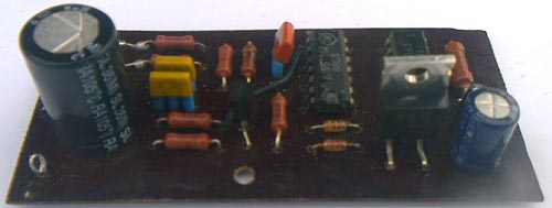
Installation of radio elements
It remains to assemble the device. Since there are not so many components in the circuit, it is possible to place them not on a printed circuit board, but by surface mounting with attachment to a radiator, that is, to the device case. We solder to the pin legs with a solid copper wire of a sufficiently large cross section, then the junction is strengthened with 5-7 turns of thin transformer wire and a small amount of POS-61 solder. After the joint has cooled down, it is insulated with a thin heat shrink tube.

High power circuits with complex secondary circuits may require the manufacture of a printed circuit board, on the edge of which transistors are placed in a row for loose attachment to the heat sink. Fiberglass with a foil thickness of at least 50 microns is suitable for making a seal, but if the coating is thinner, reinforce low-voltage circuits with copper wire jumpers.

Making a printed circuit board at home today is easy - the Sprint-Layout program allows you to draw clipping stencils for circuits of any complexity, including double-sided boards. The resulting image is printed by a laser printer on high-quality photographic paper. Then the stencil is applied to the purified and degreased copper, ironed, the paper is blurred with water. The technology was called "laser-ironing" (LUT) and is described in sufficient detail on the network.

You can etch copper residues with ferric chloride, electrolyte or even common salt, there are plenty of ways. After etching, the baked toner must be washed off, drilled mounting holes with a 1 mm drill and go through all the tracks with a soldering iron (submerged) to tin the copper of the contact pads and improve the conductivity of the channels.
When using low-power household appliances, there is often a need for a voltage converter from 12 to 220 volts. It can be a laptop, charger for a mobile phone or tablet, and even a TV with LED elements.
When is a voltage converter needed?
- Prolonged failure of the centralized power supply.
- Emergency power supply of gas boiler electronics.
- Lack of a household network of 220 volts (remote garden plot, garage cooperative).
- Automobile.
- Tourist parking (if possible, take a 12 volt battery with you).
In all these cases, it is enough to have a charged battery, and you will be able to fully use the mains electrical equipment.
note
Important! The power consumption of the device should not exceed a few hundred watts. More powerful devices will quickly drain the battery used as a donor.
In fairness, we note that for use in a car, there are power supplies and chargers that are connected to the on-board 12 volt network. They are made in the form of a connector connected to a cigarette lighter socket.
However, if you have several gadgets, you will have to splurge on buying the same number of chargers. And having one converter from 12 to 220 - you will provide complete universality of connection.
There is a wide range of ready-made converters on sale. Power varies from 150 W to several kilowatts. Of course, for each consumer power, it is necessary to select the appropriate battery.
It is also necessary to carefully read the technical specifications - often, for advertising purposes, manufacturers indicate on the packaging the peak power that the converter can withstand for only a few seconds. Operating power is typically 25% - 30% lower.
Varieties of converters 12 to 220 volts
For the right choice, check out the main types of voltage converters on the electrical market:
According to the output voltage waveform
Devices are divided into pure sine and modified sine. The difference in the waveform can be seen in the illustration.
Literally a few decades ago, no one could even think about taking electricity with them on trips. However, with the advent of the field of modern electronics, this kind of comfort has become available. Thanks to such a device as a car inverter, you can iron things, make coffee or vacuum the interior in any conditions.
The presence of a car inverter allows the driver to fully enjoy all the benefits of civilization. The principle of operation of these devices is to convert the voltage of the on-board network of a car of 12 volts into alternating current 220v.
In trucks, the power supply of the on-board network is higher, it is 24 volts, therefore, in order to connect standard devices to a car that operate from a 12v network, you will also need a 12-volt converter.
Purpose of inverters
In order for the connected device to work reliably and safely, the 12-220 volt inverter must have a protection system against overheating or heavy loads. An automobile voltage converter is connected using special clamping accessories. The inverter makes it possible to convert the voltage and provides power to various devices in a small range of about 220 V.
How is the car inverter connected? Everything is easy and simple here: using the terminals, the device is connected to a 12 V battery. If the model consumes little energy, that is, up to 12 V, then you can connect it to the cigarette lighter socket. This option is great, for example, for a laptop or electronic gadgets in a car.
Installation and connection
Proper installation, connection and further operation is the key to long and successful operation of the converter. In order for you not to be disappointed in your purchase, follow a few rules:
- It should only be installed in a dry place.
- Keep the inverter away from direct sunlight.
- Do not install the converter near heating installations.
- It is forbidden to turn on near flammable things.
Like any modern device, the car converter is equipped with a special protective system that protects against failure or damage, power surges above 12 V.
An automatic shutdown system protects against overloads, which immediately works when the voltage drops. In the event of a short circuit, the device will also turn off.
Varieties of voltage converters
Automotive inverters are divided into two types:
- With modified sine wave. That is, in these models up to 12 V there are small deviations in terms of voltage. This does not affect the power supply of simple 220 V devices, except for measuring and medical equipment.
- With a constant or normal sinusoid. They do not have deviations, all performance indicators are carried out with accuracy. Suitable for any equipment with voltage up to 220 V.
 By power, the converters are divided into the following:
- Models up to 100 watts. Work from the lighter and maintain small loadings. Suitable for charging household appliances.
- From 100 to 1500 watts. They have a wide range of applications. Battery powered. The package must include additional accessories, for example, cords, cables and others.
- From 1500 watts and above. Suitable for microwave operation away from civilization and other similar situations with a voltage of about 220 V.
You should choose such a car inverter 12 V-220 V, so that it has a power reserve. For example, some devices may consume more power than stated by the manufacturer.
Choosing a quality inverter
For greater clarity, we will analyze several models of inverters visually. We take three devices of different power:
- Power 220 - 300 W worth 1600 rubles.
- Power 600 W at the price of 1540 rubles.
- Power 2000 W worth 8280 rubles.
The first type is connected to the cigarette lighter, but only at low loads. Connecting directly to the battery will be much more reliable, before that you should start the engine. When starting the motor, the inverter must be turned off, otherwise it may burn out. 
When checking the second option, it turns out that instead of the indicated 220v or 220 V, the output is 196 Volts. 600 Watt inverter 200v, but the 2 kW inverter showed exactly 220v. Thus, powerful automotive inverters up to 2 kW reduce the life of the battery and generator, and are also expensive. Cheap inverters are very weak, so you should opt for the best models with a voltage of at least 220 V.
When choosing a high-quality and reliable voltage converter 12-220 V, the following recommendations should be considered:

Most Popular Models
In the modern world, there are a huge number of different models of automotive inverters, which differ in type, power supply and power. Low-power converters are up to 300 W. They are used to charge smartphones or laptops. This type of car inverter is connected to the cigarette lighter socket.
The medium power car inverter is designed for voltages from 300W to 1000W. These devices are connected to the battery using terminals. Below we present several popular models of this class, among which you can choose the most suitable one.
This car inverter is the best of all models. It is the optimal combination of cost, quality, body size and capabilities. We recommend choosing it. Outwardly, this device is strict and elegant. Depending on your preferences, you can choose a model with a voltage of 900 W to 1200 W. The voltage can be 12, 24, 48 V. Advantages:
- High quality screen.
- You can customize yourself.
- Several operating modes.
- You can choose as an uninterruptible power supply and charger.
The only negative is the large dimensions, but compared to the functionality, this becomes unimportant. 
Acme Power
Automotive inverter manufacturer Acme Power has an attractive appearance and a beautiful case. Here the designers did their best. The device is so convenient and compact that you want to use it again and again. The model is connected to the car battery.
The main advantages of the device are low cost, beauty, reliability and compactness. The only drawback is the low output power.
 Automotive inverters from this manufacturer are equipped with wires that are needed to connect to the battery and cigarette lighter. In addition, when connected to the cigarette lighter, do not turn on the inverter at full power. These models have compact dimensions and are suitable for a variety of purposes.
Defort
The Defort car inverter is equipped with an audible signal that indicates a decrease in battery charge or high voltage. This is an inexpensive, budget model, but with many features. There is a built-in protection against overheating, short circuits. There is a USB port.
The device at the highest level will cope with any tasks assigned to it, but more powerful devices, such as a TV or microwave, cannot be connected to it.
Thus, the car inverter must be chosen so as to take into account the power consumption of the connected device. The load must not exceed the power of the inverter.
The variety of these devices allows you to choose the device according to your preferences. All models provide maximum comfort while traveling by car. The main thing to remember is that the characteristics, compactness, reliability and quality of the converter are important parameters.