Scheme for switching on the LED from 1.5 volts. A few simple LED power circuits. Current Feedback Circuits
So we have a Panasonic RF-800UEE-K radio receiver, there is a lot of information on the Internet about all its advantages and disadvantages. Of the pluses, I note a very good quality of the tuner, a wooden (plywood) case, decent sound quality for this segment of receivers. It is very easy to disassemble, no latches, five screws on the back panel and two more screws fasten the front panel to the plywood case.
Of the shortcomings can be noted mono-sound, lack of normal bass. But there is an input and output, who lacks bass, you can connect it to external speakers.

The receiver is so successful that in order not to get into the class of multimedia centers with this device, the manufacturer cut off some of the MP3 player functionality and did not install the backlight of the receiver scale, although judging by the configuration of the front panel, it was supposed to be there. The body is glued from pressed wood chips and is quite loose, but this is easy to fix.

We glue all the seams with carpentry PVA with a "slide" until completely dry.

Then we impregnate the ends and insides with polyurethane varnish, it is very well absorbed, so you will have to put three or four plentiful layers.

After drying, the body is stretched and will begin to "sound" like the front soundboard of a guitar :-)

We measure the seat for installing the light, in our case it is a socket 90 long and 7 mm wide.

We cut the foil textolite into panels of the desired size.

The receiver is powered by 6V, for lighting I want to try orange and yellow LEDs with a forward voltage of 2.1V. I will put them in pairs, the excess voltage with such a circuit will be 1.8V, we will precipitate it on a resistor. The resistor value is calculated according to Ohm's law R=U/I. In our case, U=1.8 V, and the current I=20 mA (the maximum allowable forward current for this type of LED), it turns out that with R=90 Ohm everything should work, but we will go further and limit the current to 10-9mA, while there is no significant decrease in brightness. We get R \u003d 220 Ohm. The calculation can be made using the link at the bottom of this post.

I collect two strips of yellow and orange color on different types of LEDs. In order not to fence snot, I use one side of the false textolite as a minus, the other as a plus. 

A more intense glow was given by orange SMD LEDs.

This bar went into action. I glue it on double-sided tape, while the LEDs shine strictly at the end of the scale, there is a technological gap there.

Magic scale.

Plus output to the power knob (volume control)

Minus on the central core of the power connector. With this switching scheme, the backlight will work only when working from an external power supply; in battery mode, it will not shine, saving batteries. I think the manufacturer specifically untied two power circuits through a diode.

I don’t know about you, but in the modern world, the irrational use of batteries depresses me. We buy one and a half volt for the TV remote control, for example. It works and pleases us with its ability to switch channels without getting up from the couch. But over time, failures begin, the buttons have to be pressed repeatedly in order to achieve at least some actions, the remote control must already be held at arm's length ... The battery has run out. As always, we change what to do. But if you check the voltage in it, then it is unlikely to be at zero. Let's say one volt remains. And where to put it? It’s a pity to throw it away, but there’s nowhere to use it, you can’t power anything sensible.
It was in connection with such a monstrous waste of energy that I assembled a “joule thief” circuit to “burn out” batteries rejected by other consumers using an LED. It is called so because it is able to almost completely drain the battery, depriving it of the last joule of energy. And in general, the "flashlight of the Apocalypse" that works on any garbage is a very cool idea.
The most entertaining thing about this device is, in fact, the very fact that the LED is powered by a low voltage power source. Usually the LED needs 2.5 - 4 volts (depending on the color), if the voltage is lower, then it simply will not turn on. This circuit works as a boost converter, and its output is just as much voltage as the LED needs.
The circuit is very simple, with a minimum of details. Capacitor and diode can be omitted. 
The heart of the device is the transformer. It is wound on a ferrite ring. Rings from a used PC motherboard are well suited. 
We take an enameled copper wire (mine has a diameter of 0.3, or something - a rusty caliper), fold it in half and begin to wind it around the ring. 
A total of 20 turns are needed. Looking ahead - in the second version of the circuit there are 26 turns (for a change).
After we decide on the coils. We get two outputs from above and two from below. We clean them from varnish by any known method - sandpaper, fire, Aspirin. Using the dialing function in the multimeter, we find the combination of pins “one from above, one from below”, when it does not beep, this will be the junction of two coils. They are connected in antiphase, that is, the end of one - to the beginning of the other. 
I used the KT315G transistor, but it is possible with a different end letter. My friend, an electronics engineer, when I show him my next homemade product (or someone else's on the Internet), immediately asks how much is inside the KT315. If there is less than one, the device is useless and soulless, if there is one, but together with other transistors, then everything rests on it, on several KT315s it is good and correct, all the functionality is provided by a single transistor of this brand - the highest class.
In the second version of the scheme - KT361D. Accordingly, the polarity of switching on the LED and the battery changes.
The resistor in the base circuit is 1 kOhm.
Warm white LED with a yellow tint. In Chinese handicrafts that have flooded the market, there are no exceptions of a cold white glow, they have a bluish tint. A 100 ohm resistor is soldered under my LED. It limits the current. 

Wow, it works. A very powerful spell. 


miniaturization work. Based on such a scheme, I really want to assemble myself a flashlight-battery afterburner. The resistor in front of the LED was removed so that it shone brighter.
This circuit is another one of a series of popular converters for one battery powered LED at 1.5 volts.
Description of the operation of the converter for the LED from 1.5 volts
After connecting the power through the resistor R2, the transistor T1 opens. Further, the current flowing through the resistor R3 opens the transistor T2 and the current begins to flow through the inductor L1. The current of the inductor L1 is constantly growing and is determined by the voltage of the battery, the inductor itself, as well as the resistance value of the resistor R3.
When the current in the inductor reaches its maximum, it reverses its direction and, consequently, the voltage polarity also changes. At this moment, the transistor T1 closes through the capacitor C1, followed by the transistor T2. Current from the opposite polarity coil passes through the LED, which lights up. After a while, transistors T1 and T2 turn on and the cycle repeats again.
The converter is able to increase the voltage up to 10 volts, so that it can easily light even two or three diodes at full brightness. The current flowing through the LED can be regulated within certain limits by changing the resistance of the resistor R3.
The converter for the LED is assembled on a single-sided board


If you ever want to power an LED with a single battery, sooner or later you will stumble upon a circuit called Joule Thief - thief of joules. This circuit is good for many: a small number of parts, you can use a dead battery, the assembled design is compact and will work from a battery with a voltage of only 0.6V. The classic scheme of this device can be found on Wikipedia. There are many variants of this scheme, attempts to optimize it. I will show you one of the variants of this design, which will allow you to light two 3-watt LEDs connected in series. Everything was put together quickly. Taking into account the rewind of the throttle, it took 20 minutes. 
What you need for assembly:
Soldering iron, not a lot of solder and wires. Battery 1.5V or less, firm hands.
Transistor. I used KT630,


its maximum operating frequency is large, the collector current is higher than that recommended in standard circuits. In principle, you can use any NPN transistor with a gain of at least 150, for example, 2SC1815. One 10 kΩ variable resistor.

One electrolytic capacitor 47uF at 25V. A larger capacitor takes longer to charge and reduces the brightness of the glow. Any one diode with a reverse voltage of at least 100 V, because without load, the capacitor charges up to 30-45V.

One 0.01uF capacitor. Two 3 watt LEDs connected in series. Mounted on a radiator from a computer processor.
One group stabilization choke from a computer PSU.

You can use any ferrite ring that is at hand. I used the choke from the PSU, simply because it was. I didn’t count the number of turns, I just wound the entire wire from the ring (there are two wires of different sections) and wound it again, bifilarly.


The winding, wound with a wire of a smaller cross section, was included in the base circuit of the transistor. Accordingly, the second winding was included in the collector circuit. It is important that the beginning of one winding is connected to the end of the other, as shown in the diagram. you can wind a winding on a ferrite rod with a tap from the required number of turns, or in general, make a coil without a core.
Unlike the standard circuit, here, the load is connected between the base and the collector. The efficiency of the circuit depends on the capacitor, which is connected in parallel with the load. Such a load switching circuit was made in an attempt to use the OEMF that occurs in the L2 coil.
The video shows that when the resistor R1 is closed, the brightness of the glow increases.
Despite the rich selection of LED flashlights of various designs in stores, radio amateurs are developing their own circuits for powering white super-bright LEDs. Basically, the task comes down to how to power the LED with just one battery or accumulator, to conduct practical research.
After a positive result is obtained, the circuit is disassembled, the parts are put into a box, the experience is completed, and moral satisfaction sets in. Often research stops there, but sometimes the experience of assembling a particular node on a breadboard turns into a real design, made according to all the rules of art. The following are a few simple circuits developed by radio amateurs.
In some cases, it is very difficult to establish who is the author of the scheme, since the same scheme appears on different sites and in different articles. Often the authors of articles honestly write that this article was found on the Internet, but who published this scheme for the first time is unknown. Many circuits are simply copied from the boards of the same Chinese lanterns.
Why converters are needed
The thing is that the direct voltage drop across, as a rule, is not less than 2.4 ... 3.4V, therefore it is simply impossible to light the LED from one battery with a voltage of 1.5V, and even more so from a battery with a voltage of 1.2V. There are two exits. Either use a battery of three or more galvanic cells, or build at least the simplest one.
It is the converter that will allow you to power the flashlight with just one battery. This solution reduces the cost of power supplies, and in addition allows you to make fuller use: many converters are operational with a deep battery discharge up to 0.7V! Using a converter also allows you to reduce the size of the flashlight.
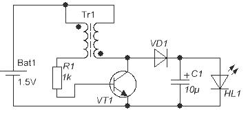
The circuit is a blocking generator. This is one of the classic electronics circuits, so with proper assembly and serviceable parts, it starts working right away. The main thing in this circuit is to wind the transformer Tr1 correctly, not to confuse the phasing of the windings.

As a core for a transformer, you can use a ferrite ring from a board from a bad one. It is enough to wind a few turns of insulated wire and connect the windings, as shown in the figure below.

The transformer can be wound with a winding wire of the PEV or PEL type with a diameter of not more than 0.3 mm, which will allow you to lay a slightly larger number of turns on the ring, at least 10 ... 15, which will somewhat improve the operation of the circuit.
The windings should be wound in two wires, and then connect the ends of the windings, as shown in the figure. The beginning of the windings in the diagram is shown by a dot. As you can use any low-power transistor n-p-n conductivity: KT315, KT503 and the like. At present, it is easier to find an imported transistor, such as BC547.
If there is no n-p-n structure transistor at hand, then you can use, for example, KT361 or KT502. However, in this case, you will have to change the polarity of the battery.
Resistor R1 is selected according to the best glow of the LED, although the circuit works even if it is replaced simply by a jumper. The above scheme is intended simply "for the soul", for experiments. So after eight hours of continuous operation on one LED, the battery from 1.5V “sits down” to 1.42V. We can say that it is almost not discharged.
To study the load capacity of the circuit, you can try to connect several more LEDs in parallel. For example, with four LEDs, the circuit continues to work quite stably, with six LEDs the transistor starts to heat up, with eight LEDs the brightness drops noticeably, the transistor heats up very strongly. And the scheme, nevertheless, continues to work. But this is only in the order of scientific research, since the transistor in this mode will not work for a long time.
If you plan to create a simple flashlight based on this circuit, then you will have to add a couple more details, which will ensure a brighter glow of the LED.
It is easy to see that in this circuit the LED is powered not by pulsating, but by direct current. Naturally, in this case, the brightness of the glow will be somewhat higher, and the level of pulsations of the emitted light will be much less. Any high-frequency diode is suitable as a diode, for example, KD521 ().
Choke converters
Another simple circuit is shown in the figure below. It is somewhat more complicated than the circuit in Figure 1, contains 2 transistors, but instead of a transformer with two windings, it has only an L1 inductor. Such a choke can be wound on a ring from the same energy-saving lamp, for which it will be necessary to wind only 15 turns of a winding wire with a diameter of 0.3 ... 0.5 mm.

With the specified choke setting, a voltage of up to 3.8V can be obtained on the LED (forward voltage drop across the 5730 LED is 3.4V), which is enough to power a 1W LED. Adjusting the circuit consists in selecting the capacitance of the capacitor C1 in the range of ± 50% according to the maximum brightness of the LED. The circuit is operational when the supply voltage drops to 0.7V, which ensures maximum use of the battery capacity.
If the considered circuit is supplemented with a rectifier on diode D1, a filter on capacitor C1, and a zener diode D2, you get a low-power power supply that can be used to power circuits on an op-amp or other electronic components. In this case, the inductance of the inductor is selected within 200 ... 350 μH, the diode D1 with a Schottky barrier, the zener diode D2 is selected according to the voltage of the fed circuit.

With a successful combination of circumstances, using such a converter, you can get a voltage of 7 ... 12V at the output. If you intend to use the converter to power only the LEDs, the zener diode D2 can be excluded from the circuit.
All the considered circuits are the simplest sources of voltage: the current limitation through the LED is carried out in much the same way as it is done in various key fobs or in lighters with LEDs.
The LED through the power button, without any limiting resistor, is powered by 3 ... 4 small disk batteries, the internal resistance of which limits the current through the LED at a safe level.
Current Feedback Circuits
And the LED is, after all, a current device. It is not for nothing that the direct current is indicated in the documentation for LEDs. Therefore, real circuits for powering LEDs contain current feedback: as soon as the current through the LED reaches a certain value, the output stage is disconnected from the power supply.
Voltage stabilizers also work exactly the same, only there is voltage feedback. The circuit for powering LEDs with current feedback is shown below.

Upon closer examination, you can see that the basis of the circuit is the same blocking oscillator, assembled on the transistor VT2. Transistor VT1 is the control in the feedback circuit. Feedback in this scheme works as follows.
LEDs are powered by voltage that is stored on an electrolytic capacitor. The capacitor is charged through the diode with a pulsed voltage from the collector of the transistor VT2. The rectified voltage is used to power the LEDs.
The current through the LEDs passes through the following path: the positive capacitor plate, LEDs with limiting resistors, the current feedback resistor (sensor) Roc, the negative plate of the electrolytic capacitor.
In this case, a voltage drop is created on the feedback resistor Uoc=I*Roc, where I is the current through the LEDs. With increasing voltage across (the oscillator still works and charges the capacitor), the current through the LEDs increases, and, consequently, the voltage across the feedback resistor Roc also increases.
When Uoc reaches 0.6V, transistor VT1 opens, closing the base-emitter junction of transistor VT2. Transistor VT2 closes, the blocking generator stops and stops charging the electrolytic capacitor. Under the influence of the load, the capacitor is discharged, the voltage across the capacitor drops.
Reducing the voltage on the capacitor leads to a decrease in the current through the LEDs, and, as a result, a decrease in the feedback voltage Uoc. Therefore, the transistor VT1 closes and does not interfere with the operation of the blocking generator. The generator starts up and the whole cycle repeats over and over again.
By changing the resistance of the feedback resistor, it is possible to change the current through the LEDs over a wide range. Such circuits are called switching current stabilizers.
Integrated current stabilizers
Currently, current stabilizers for LEDs are produced in an integrated version. Examples include specialized microcircuits ZXLD381, ZXSC300. The circuits shown below are taken from the datasheets (DataSheet) of these microcircuits.

The figure shows the device of the ZXLD381 chip. It contains a PWM generator (Pulse Control), a current sensor (Rsense) and an output transistor. There are only two hanging parts. This is an LED and a choke L1. A typical switching circuit is shown in the following figure. The microcircuit is produced in the SOT23 package. The generation frequency of 350KHz is set by internal capacitors, it cannot be changed. The efficiency of the device is 85%, starting under load is possible already at a supply voltage of 0.8V.

The forward voltage of the LED should be no more than 3.5V, as indicated in the bottom line below the figure. The current through the LED is controlled by changing the inductance of the inductor, as shown in the table on the right side of the figure. The middle column shows the peak current, the last column shows the average current through the LED. To reduce the level of pulsations and increase the brightness of the glow, it is possible to use a rectifier with a filter.

Here we use a LED with a forward voltage of 3.5V, a high-frequency diode D1 with a Schottky barrier, a capacitor C1, preferably with a low value of equivalent series resistance (low ESR). These requirements are necessary in order to increase the overall efficiency of the device, to heat the diode and capacitor as little as possible. The output current is selected by selecting the inductance of the inductor depending on the power of the LED.
It differs from the ZXLD381 in that it does not have an internal output transistor and a current sense resistor. This solution allows you to significantly increase the output current of the device, and therefore use a higher power LED.

An external resistor R1 is used as a current sensor, by changing the value of which you can set the required current depending on the type of LED. The calculation of this resistor is made according to the formulas given in the datasheet for the ZXSC300 chip. We will not give these formulas here, if necessary, it is easy to find a datasheet and peep the formulas from there. The output current is limited only by the parameters of the output transistor.
When you first turn on all the described circuits, it is advisable to connect the battery through a 10 Ohm resistor. This will help to avoid the death of the transistor if, for example, the transformer windings are not connected correctly. If the LED lights up with this resistor, then the resistor can be removed and further settings can be made.
Boris Aladyshkin