Homemade circuits for 7805. Voltage stabilizer and current stabilizer. Stabilizer with smooth output to rated voltage
It is known that the brightness of an LED depends very much on the current flowing through it. At the same time, the LED current depends very sharply on the supply voltage. This results in noticeable brightness ripples even with slight power instability.
But ripple is not scary, what’s much worse is that the slightest increase in the supply voltage can lead to such a strong increase in the current through the LEDs that they simply burn out.
To prevent this, LEDs (especially powerful ones) are usually powered through special circuits - drivers, which are essentially current stabilizers. This article will discuss circuits of simple current stabilizers for LEDs (on transistors or common microcircuits).
There are also very similar LEDs - SMD 5730 (without the 1 in the name). They have a power of only 0.5 W and a maximum current of 0.18 A. So don’t get confused.
Since when LEDs are connected in series, the total voltage will be equal to the sum of the voltages on each of the LEDs, the minimum supply voltage of the circuit should be: Upit = 2.5 + 12 + (3.3 x 10) = 47.5 Volts.
You can calculate the resistance and power of the resistor for other current values using the simple Regulator Design program (download). 
Obviously, the higher the output voltage of the stabilizer, the more heat will be generated at the current-setting resistor and, therefore, the worse the efficiency. Therefore, for our purposes, the LM7805 is better than the LM7812.
LM317
The linear current stabilizer for LEDs based on LM317 is no less effective. Typical connection diagram: 
The simplest LM317 connection circuit for LEDs, which allows you to assemble a powerful lamp, consists of a rectifier with a capacitive filter, a current stabilizer and 93 LEDs SMD 5630. Here we use MXL8-PW35-0000 (3500K, 31 Lm, 100 mA, 3.1 V, 400 mW, 5.3x3 mm). 
If such a large garland of LEDs is not needed, then you will have to add a ballast resistor or capacitor to the LM317 driver to power the LEDs (to suppress excess voltage). We discussed how to do this in great detail in.
The disadvantage of such a current driver circuit for LEDs is that when the voltage in the network increases above 235 volts, the LM317 will be outside the design operating mode, and when it drops to ~208 volts and below, the microcircuit completely ceases to stabilize and the ripple depth will entirely depend from container C1.
Therefore, such a lamp should be used where the voltage is more or less stable. And you should not skimp on the capacity of this capacitor. The diode bridge can be taken ready-made (for example, a miniature MB6S) or assembled from suitable diodes (U arr. at least 400 V, forward current >= 100 mA). The ones mentioned above are perfect 1N4007.
As you can see, the circuit is simple and does not contain any expensive components. Here are the current prices (and they will likely continue to decline):
| Name | characteristics | price |
|---|---|---|
| SMD 5630 | LED, 3.3V, 0.15A, 0.5W | 240 rub. / 1000pcs. |
| LM317 | 1.25-37V, >1.5A | 112 rub. / 10 pieces. |
| MB6S | 600V, 0.5A | 67 rub. / 20pcs. |
| 120μF, 400V | 18x30mm | 560 rub. / 10 pieces. |
Thus, by spending a total of 1000 rubles, you can collect a dozen 30-watt (!!!) non-flicker (!!!) light bulbs. And since the LEDs do not operate at full power, and the only electrolyte does not overheat, these lamps will last almost forever.
Instead of a conclusion
The disadvantages of the circuits presented in the article include low efficiency due to the waste of power on the control elements. However, this is typical of all linear current stabilizers.
Low efficiency is unacceptable for devices powered by autonomous current sources (lamps, flashlights, etc.). A significant increase in efficiency (90% or more) can be achieved by using.

Currently, it is difficult to find any electronic device that does not use a stabilized power supply. Mainly as a power source, for the vast majority of various radio-electronic devices designed to operate from 5 volts, the best option would be to use a three-pin integrated 78L05.
Description of stabilizer 78L05
This stabilizer is inexpensive and easy to use, which makes it easier to design radio-electronic circuits with a significant number of printed circuit boards, to which an unstabilized DC voltage is supplied, and each board has its own stabilizer mounted separately.
The microcircuit - stabilizer 78L05 (7805) has thermal protection, as well as a built-in system that protects the stabilizer from overcurrent. However, for more reliable operation, it is advisable to use a diode to protect the stabilizer from a short circuit in the input circuit.
Technical parameters and pinout of stabilizer 78L05:
- Input voltage: 30 volts.
- Output voltage: 5.0 volts.
- Output current (maximum): 100 mA.
- Current consumption (stabilizer): 5.5 mA.
- Permissible input-output voltage difference: 1.7 volts.
- Operating temperature: -40 to +125 °C.


Multifunctional device for testing transistors, diodes, thyristors...
Analogs of stabilizer 78L05 (7805)
There are two types of this microcircuit: powerful 7805 (load current up to 1A) and low-power 78L05 (load current up to 0.1A). The foreign analogue of 7805 is ka7805. Domestic analogues for 78L05 are KR1157EN5, and for 7805 - 142EN5
Connection diagram 78L05
A typical connection circuit for the 78L05 stabilizer (according to the datasheet) is easy and does not require a large number of additional radio elements.

C1 at the input is necessary to eliminate RF interference when applying input voltage. Capacitor C2 at the output of the stabilizer, as in any other power source, ensures the stability of the power supply during sudden changes in load current, and also reduces the degree of ripple.
When designing a power supply, it is necessary to keep in mind that for stable operation of the 78L05 stabilizer, the input voltage must be at least 7 and no more than 20 volts.
Below are some examples of using the 78L05 Integrated Regulator.
Laboratory power supply for 78L05
This circuit is distinguished by its originality, due to the non-standard use of the microcircuit, the source of the reference voltage of which is the 78L05 stabilizer. Since the maximum permissible input voltage for the 78L05 is 20 volts, to prevent the 78L05 from failing, a parametric stabilizer was added to the circuit using the zener diode VD1 and resistor R1.

The TDA2030 chip is connected as a non-inverting amplifier. With this connection, the gain is 1+R4/R3 (in this case 6). Thus, the voltage at the output of the power supply, when the resistance of resistor R2 changes, will change from 0 to 30 volts (5 volts x 6). If you need to change the maximum output voltage, this can be done by selecting the appropriate resistance of resistor R3 or R4.

Kit for assembling an adjustable power supply...
Transformerless 5 volt power supply
this is characterized by increased stability, lack of heating of the elements and consists of accessible radio components.

The structure of the power supply includes: a power indicator on the HL1 LED, instead of a conventional transformer - a damping circuit on elements C1 and R2, a diode rectifier bridge VD1, capacitors to reduce ripple, a 9-volt zener diode VD2 and an integrated voltage regulator 78L05 (DA1). The need for a zener diode is due to the fact that the voltage from the output of the diode bridge is approximately 100 volts and this can damage the 78L05 stabilizer. You can use any zener diode with a stabilization voltage from 8...15 volts.
Attention!Since the circuit is not galvanically isolated from the mains, care should be taken when setting up and using the power supply.
Simple regulated power supply on the 78L05

The adjustable voltage range in this circuit is from 5 to 20 volts. The output voltage is changed using variable resistor R2. The maximum load current is 1.5 amperes. It is best to replace the 78L05 stabilizer with 7805 or its domestic analogue KR142EN5A. Transistor VT1 can be replaced with. It is advisable to place the powerful transistor VT2 on a radiator with an area of at least 150 square meters. cm.

Simple and intuitive operation, fast and accurate selection of voltage and current...
Universal charger circuit
This charger circuit is quite simple and universal. Charging allows you to charge all types of batteries: lithium, nickel, as well as small lead batteries used in uninterruptible power supplies.

It is known that when charging batteries, a stable charging current is important, which should be approximately 1/10 of the battery capacity. The constant charging current is ensured by the 78L05 (7805) stabilizer. The charger has 4 charging current ranges: 50, 100, 150 and 200 mA, which are determined by resistances R4…R7, respectively. Based on the fact that the output of the stabilizer is 5 volts, then to obtain, say, 50 mA, a 100 Ohm resistor is needed (5V / 0.05 A = 100) and so on for all ranges.
The circuit is also equipped with an indicator built on two transistors VT1, VT2 and an LED HL1. The LED goes off when the battery is charging.

charging current: 500 mA/h, 1000 mA/h. charging modes with constant...
Adjustable current source
Due to negative feedback through the load resistance, the voltage Uin is located at input 2 (inverting) of the TDA2030 (DA2) microcircuit. Under the influence of this voltage, a current flows through the load: Ih = Uin / R2. Based on this formula, the current flowing through the load does not depend on the resistance of this load.

Thus, by changing the voltage supplied from variable resistor R1 to input 1 of DA2 from 0 to 5 V, with a constant value of resistor R2 (10 Ohms), you can change the current flowing through the load in the range from 0 to 0.5 A.
A similar circuit can be successfully used as a charger for charging all kinds of batteries. The charging current is constant during the entire charging process and does not depend on the level of discharge of the battery or on the variability of the supply network. The charge current limit can be changed by decreasing or increasing the resistance of resistor R2.
(161.0 KiB, downloads: 6,505)
The L7805 CV integrated stabilizer is a conventional three-terminal 5V positive voltage regulator. Produced by STMircoelectronics, approximate price is about $1. Made in a standard TO-220 package (see figure), in which many transistors are made, however, its purpose is completely different.
In the marking of the 78XX series the last two digits indicate stabilized voltage rating, for example:
- 7805 - 5 V stabilization;
- 7812 - 12 V stabilization;
- 7815 - stabilization at 15 V, etc.
The 79 series is designed for negative output voltage.
Is used for voltage stabilization in various low-voltage circuits. It is very convenient to use when it is necessary to ensure the accuracy of the supplied voltage; there is no need to install complex stabilization circuits, and all this can be replaced with one microcircuit and a couple of capacitors.
 Connection diagram L 7805 CV It’s quite simple; to work, you need to place capacitors at the input of 0.33 µF, and at the output of 0.1 µF, according to the datasheet. It is important during installation or design to place the capacitors as close as possible to the terminals of the microcircuit. This is done to ensure the maximum level of stabilization and reduce interference.
By characteristics The L7805CV stabilizer is operational when an input DC voltage is supplied in the range from 7.5 to 25 V. The output of the microcircuit will be a stable DC voltage of 5 Volts. This is the beauty of the L7805CV chip.
 How to check functionality microcircuits? To begin with, you can simply ring the terminals with a multimeter; if in at least one case a short is observed, then this clearly indicates a malfunction of the element. If you have a power source of 7 V or higher, you can assemble a circuit according to the datasheet given above and apply power to the input; at the output, use a multimeter to record the voltage at 5 V, so the element is absolutely operational. The third method is more labor-intensive if you do not have a power source. However, in this case, you will also receive a 5 V power supply in parallel. It is necessary to assemble a circuit with a rectifier bridge according to the figure presented below.
Needed for verification a step-down transformer with a transformation ratio of 18 - 20 and a rectifier bridge, a further standard kit, two capacitors for the stabilizer and that’s it, the 5 V power supply is ready. The capacitor values here are overestimated in relation to the L7805 connection diagram in the datasheet, this is due to the fact that it is better to smooth out voltage ripples after the rectifier bridge. For safer operation, it is advisable to add an indication to visualize the device being turned on. Then the diagram will look like this:
If there are a lot of capacitors or any other capacitive load on the load, you can protect the stabilizer with a reverse diode to prevent the element from burning out when the capacitors are discharged.
The big advantage of the microcircuit is Quite lightweight design and ease of use, if you need power of one value. Circuits sensitive to voltage values must be equipped with such stabilizers in order to protect elements sensitive to voltage surges.
Main settings stabilizer L7805CV:
- Input voltage - from 7 to 25 V;
- Power dissipation - 15 W;
- Output voltage - 4.75...5.25 V;
- Output current - up to 1.5 A.
 Characteristics of the microcircuit shown in the table below, these values are valid subject to certain conditions. Namely, the temperature of the microcircuit is in the range from 0 to 125 degrees Celsius, the input voltage is 10 V, the output current is 500 mA (unless otherwise specified in the conditions, the Test conditions column), and the standard body kit with capacitors at the input is 0.33 μF and at the output 0 ,1 µF.
The table shows that the stabilizer behaves perfectly when powered at the input from 7 to 20 V and the output will stably output from 4.75 to 5.25 V. On the other hand, supplying higher values leads to a more significant spread of output values , therefore, above 25 V is not recommended, and a decrease in the input of less than 7 V will generally lead to the absence of voltage at the output of the stabilizer.
, more than 5 W, it is necessary to install a radiator on the chip to avoid overheating of the stabilizer, the design allows this to be done without any questions. Naturally, such a stabilizer is not suitable for more precise (precision) equipment, because has a significant spread in the rated voltage when the input voltage changes.Since the stabilizer is linear, it makes no sense to use it in powerful circuits; stabilization based on pulse-width modeling will be required, but for powering small devices As phones, children's toys, radio tape recorders and other gadgets, the L7805 is quite suitable. The domestic analogue is KR142EN5A or in common parlance “KRENKA”. In terms of cost, the analogue is also in the same category.
Schematic diagram of a simple and reliable voltage stabilizer from 8...15V to stable 5V. Built on the L7805 integrated circuit. The stabilizer is suitable for powering digital equipment, microcontrollers, for charging phones and other devices from a stable voltage of 5V.
78XX series chips contain several built-in protections:
- Output voltage and current protection;
- Thermal protection (against overheating above +125 °C);
- Built-in powerful diode (protects against reverse current).
Schematic diagram
Figure 1 shows a schematic diagram of a homemade voltage stabilizer based on the L7805 chip. The circuit does not contain a large number of parts, which can be further reduced if reverse polarity protection at the input (D1) and voltage indication at the output (R1, LED1) are not needed.
Rice. 1. Schematic diagram of a simple and reliable 5V voltage stabilizer (L7805).
Details
A Schottky diode can be installed as D1; in the circuit it acts as protection against power supply reverse polarity, or as a rectifier if the circuit is connected directly to the secondary winding of a step-down network transformer. Diode D2 protects the output of the microcircuit from reverse voltage.
Capacitors C2 and C3 are film or ceramic, non-polar. Electrolytic capacitor C1 can be installed with a capacity of 50 µF or more, and for C4 10-22 µF will be sufficient. LED1 is used to indicate the presence of 5V voltage; any LED with a green glow will do here.
This scheme is simple and time-tested. Instead of the L7805 microcircuit, you can install other microcircuits of this series and thus obtain a voltage stabilizer for other voltages.
In discussions of electrical circuits, the terms "voltage stabilizer" and "current stabilizer" are often used. But what's the difference between them? How do these stabilizers work? Which circuit requires an expensive voltage stabilizer, and where a simple regulator is enough? You will find answers to these questions in this article.
Let's look at a voltage stabilizer using the LM7805 device as an example. Its characteristics indicate: 5V 1.5A. This means it stabilizes the voltage and precisely up to 5V. 1.5A is the maximum current that the stabilizer can conduct. Peak current. That is, it can deliver 3 milliamps, 0.5 amperes, and 1 ampere. As much current as the load requires. But no more than one and a half. This is the main difference between a voltage stabilizer and a current stabilizer.
Types of voltage stabilizers
There are only 2 main types of voltage stabilizers:
- linear
- pulse
Linear voltage stabilizers
For example, microcircuits BANK or , LM1117, LM350.
By the way, KREN is not an abbreviation, as many people think. This is a reduction. A Soviet stabilizer chip similar to the LM7805 was designated KR142EN5A. Well, there is also KR1157EN12V, KR1157EN502, KR1157EN24A and a bunch of others. For brevity, the entire family of microcircuits began to be called “KREN”. KR142EN5A then turns into KREN142.
Soviet stabilizer KR142EN5A. Analogous to LM7805.

Stabilizer LM7805
The most common type. Their disadvantage is that they cannot operate at a voltage lower than the declared output voltage. If the voltage stabilizes at 5 volts, then it needs to be supplied at least one and a half volts more to the input. If we apply less than 6.5 V, then the output voltage will “sag” and we will no longer receive 5 V. Another disadvantage of linear stabilizers is strong heating under load. Actually, this is the principle of their operation - everything above the stabilized voltage simply turns into heat. If we supply 12 V to the input, then 7 V will be spent on heating the case, and 5 will go to the consumer. In this case, the case will heat up so much that without a heatsink the microcircuit will simply burn out. All this leads to another serious drawback - a linear stabilizer should not be used in battery-powered devices. The energy of the batteries will be spent on heating the stabilizer. Pulse stabilizers do not have all these disadvantages.
Switching voltage stabilizers
Switching stabilizers- do not have the disadvantages of linear ones, but are also more expensive. This is no longer just a chip with three pins. They look like a board with parts.

One of the options for the implementation of a pulse stabilizer.
Switching stabilizers There are three types: step-down, step-up and omnivorous. The most interesting ones are omnivores. Regardless of the input voltage, the output will be exactly what we need. An omnivorous pulse generator doesn’t care if the input voltage is lower or higher than required. It automatically switches to the mode of increasing or decreasing the voltage and maintains the set output. If the specifications state that the stabilizer can be supplied with 1 to 15 volts at the input and the output will be stable at 5, then it will be so. In addition, heating pulse stabilizers so insignificant that in most cases it can be neglected. If your circuit will be powered by batteries or placed in a closed case, where strong heating of the linear stabilizer is unacceptable, use a pulsed one. I use custom switching voltage stabilizers for pennies, which I order from Aliexpress. You can buy it.
Fine. What about the current stabilizer?
I won't discover America if I say that current stabilizer stabilizes the current.
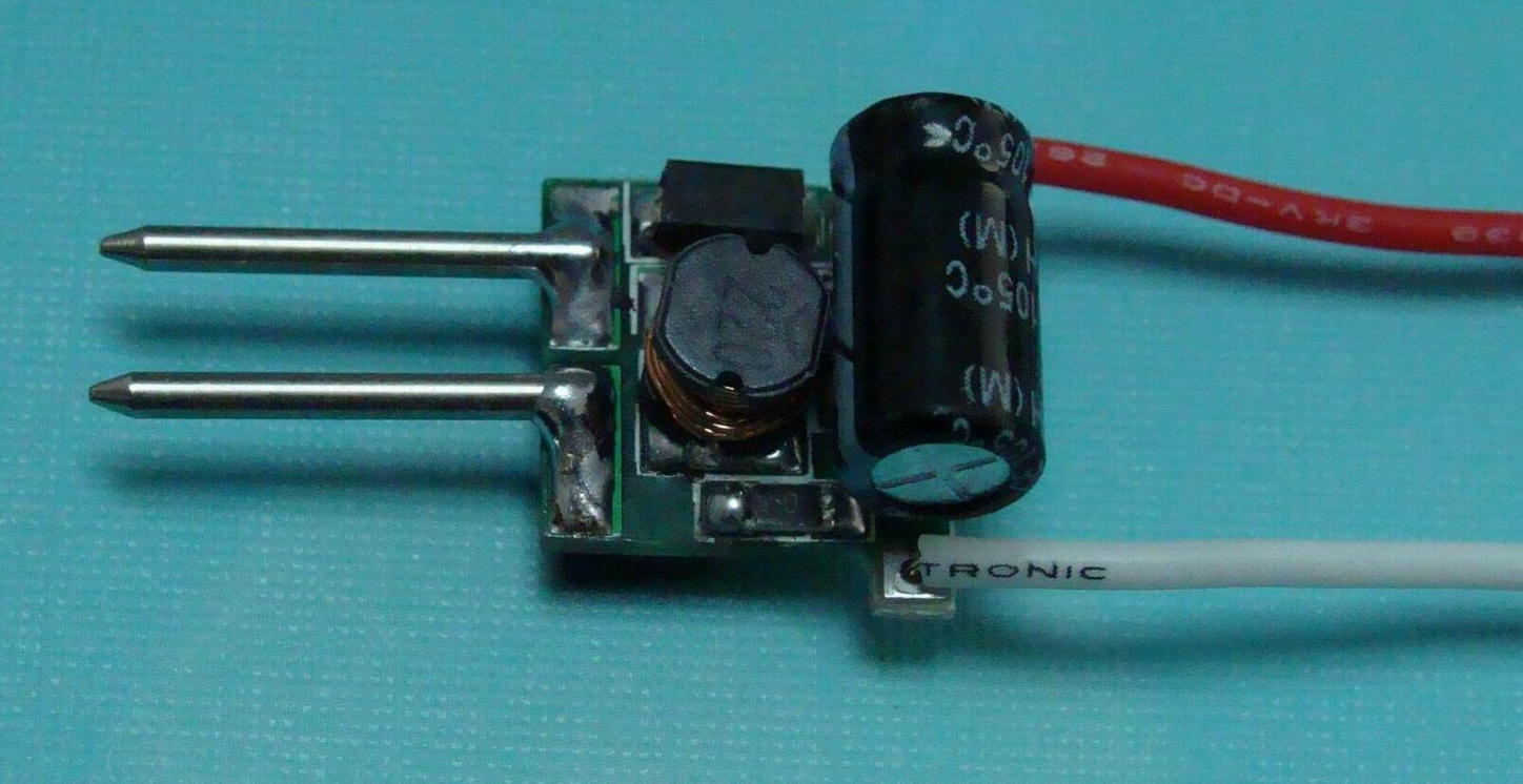
Current stabilizers are also sometimes called LED drivers. Externally, they are similar to pulse voltage stabilizers. Although the stabilizer itself is a small microcircuit, everything else is needed to ensure the correct operating mode. But usually the entire circuit is called a driver at once.

This is what a current stabilizer looks like. Circled in red is the same circuit that is the stabilizer. Everything else on the board is wiring.
So. The driver sets the current. Stable! If it is written that the output current will be 350mA, then it will be exactly 350mA. But the output voltage may vary depending on the voltage required by the consumer. Let's not get into the wilds of theories about that. how it all works. Let's just remember that you don't regulate the voltage, the driver will do everything for you based on the consumer.
Well, why is all this necessary?
Now you know how a voltage stabilizer differs from a current stabilizer and you can navigate their diversity. Perhaps you still don’t understand why these things are needed.
Example: you want to power 3 LEDs from the car's on-board power supply. As you can learn from, for an LED it is important to control the current strength. We use the most common option for connecting LEDs: 3 LEDs and a resistor are connected in series. Supply voltage - 12 volts.
We limit the current to the LEDs with a resistor so that they do not burn out. Let the voltage drop across the LED be 3.4 volts.
After the first LED, 12-3.4 = 8.6 volts remains.
We have enough for now.
On the second, another 3.4 volts will be lost, that is, 8.6-3.4 = 5.2 volts will remain.
And there will be enough for the third LED too.
And after the third there will be 5.2-3.4 = 1.8 volts.
If you want to add a fourth LED, it won’t be enough.
If the supply voltage is raised to 15V, then it will be enough. But then the resistor will also need to be recalculated. A resistor is the simplest current stabilizer (limiter). They are often placed on the same tapes and modules. It has a minus - the lower the voltage, the less current on the LED will be (Ohm’s law, you can’t argue with it). This means that if the input voltage is unstable (this is usually the case in cars), then you first need to stabilize the voltage, and then you can limit the current with a resistor to the required values. If we use a resistor as a current limiter where the voltage is not stable, we need to stabilize the voltage.
It is worth remembering that it makes sense to install resistors only up to a certain current strength. After a certain threshold, the resistors begin to get very hot and you have to install more powerful resistors (why a resistor needs power is described in the article about this device). Heat generation increases, efficiency decreases.
Also called an LED driver. Often, those who are not well versed in this, a voltage stabilizer is simply called an LED driver, and a pulse current stabilizer is called good LED driver. It immediately produces stable voltage and current. And it hardly gets hot. This is what it looks like: