Voltage stabilizer at 431. Checking the tl431 reference voltage source. Performance characteristics tl431
Good afternoon friends!
Today we will get acquainted with another piece of hardware that is used in computer technology. It is not used as often as, say, or, but also noteworthy.
What is this TL431 reference voltage source?
In power supplies for personal computers, you can find a reference voltage source chip (ION) TL431.
You can think of it as an adjustable zener diode.
But this is precisely a microcircuit, since more than a dozen transistors are placed in it, not counting other elements.
A zener diode is such a thing that maintains (seeks to maintain) a constant voltage across the load. "Why is this necessary?" - you ask.
The fact is that the microcircuits that make up a computer - both large and small - can only work in a certain (not very large) range of supply voltages. If the range is exceeded, their failure is very likely.
Therefore, in (not only computer) circuits and components are used to stabilize the voltage.
With a certain voltage range between the anode and the cathode (and a certain range of cathode currents), the microcircuit provides at its output ref a reference voltage of 2.5 V relative to the anode.
Using external circuits (resistors), you can vary the voltage between the anode and cathode in a fairly wide range - from 2.5 to 36 V.
Thus, we do not need to look for zener diodes for a specific voltage! You can simply change the resistor values and get the voltage level we need.
 In computer power supplies, there is a standby voltage source + 5VSB.
If the power supply plug is plugged into the network, it is present on one of the pins of the main power connector - even if the computer is not turned on.
At the same time, part of the components of the computer motherboard is under this voltage..
It is with the help of it that the main part of the power supply is launched - by a signal from the motherboard. The TL431 chip is also often involved in the formation of this voltage.
 When it fails, the value of the standby voltage may differ - and quite strongly - from the nominal value.
How can this threaten us?
If the voltage + 5VSB is more than necessary, the computer may “freeze”, as part of the motherboard chipset is powered by increased voltage.
Sometimes this behavior of the computer misleads an inexperienced repairman. After all, he measured the main supply voltages of the power supply +3.3 V, +5 V, +12 V - and saw that they were within tolerance.
He starts digging elsewhere and spends a lot of time troubleshooting. And you just had to measure the voltage of the source on duty!
Recall that the +5VSB voltage must be within 5% tolerance, i.e. lie in the range of 4.75 - 5.25 V.
If the voltage of the standby source is less than necessary, the computer may not start at all.
How to check TL431?
 It is impossible to “ring out” this microcircuit as a regular zener diode.
To make sure it works, you need to assemble a small circuit for testing.
In this case, the output voltage in the first approximation is described by the formula
Vo = (1 + R2/R3) * Vref (see datasheet*), where Vref is a reference voltage of 2.5 V.

When the button S1 is closed, the output voltage will have a value of 2.5 V (reference voltage), when it is released, it will have a value of 5 V.
Thus, by pressing and depressing the S1 button and measuring the signal at the output of the circuit, you can verify the health (or malfunction) of the microcircuit.
The test circuit can be made as a separate module using a 16-pin DIP connector with a 2.5mm pitch. Power and tester probes are connected to the output terminals of the module.
To check the microcircuit, you need to insert it into the connector, press the button and look at the tester display.
If the chip is not inserted into the socket, the output voltage will be approximately 10 V.
That's all! Simple, isn't it?
*Datasheet is reference data (data sheets) for electronic components. They can be found with a search engine on the Internet.
Victor Geronda was with you. See you on the blog!
The production of integrated circuits began in the distant 1978 and continues to this day. The microcircuit makes it possible to manufacture various types of alarms and chargers for everyday use. The tl431 chip has found wide application in household appliances: monitors, tape recorders, tablets. TL431 is a kind of programmable voltage regulator.
Switching scheme and principle of operation
The principle of operation is quite simple. The stabilizer has a constant value of the reference voltage, and if the supplied voltage is less than this value, then the transistor will be closed and will not allow the passage of current. This can be clearly seen in the following diagram.
If this value is exceeded, the adjustable zener diode will open the P-N junction of the transistor, and the current will flow further to the diode, from plus to minus. The output voltage will be constant. Accordingly, if the current falls below the value of the reference voltage, the controlled operational amplifier will close.
Pinout and technical parameters
The operational amplifier is available in different packages. Initially, it was the TO-92 case, but over time it was replaced by a newer version of the SOT-23. The pinout and types of cases are shown below, starting from the most “ancient” and ending with the updated version.
In the figure, you can see that for tl431, the pinout changes depending on the type of case. tl431 has domestic analogues KR142EN19A, KR142EN19A. There are also foreign analogues of tl431: KA431AZ, KIA431, LM431BCM, AS431, 3s1265r, which are in no way inferior to the domestic version.
Feature TL431
This op-amp works with voltages from 2.5V to 36V. The current of the amplifier ranges from 1A to 100 mA, but there is one important nuance: if stability is required in the operation of the stabilizer, then the current strength should not fall below 5 mA at the input. TL431 has a reference voltage value, which is determined by the 6th letter in the marking:
- If there is no letter, then the accuracy is - 2%.
- The letter A in the marking indicates - 1% accuracy.
- The letter B speaks of - 0.5% accuracy.
A more detailed technical characteristic is shown in Fig. 4
In the description of tl431A, you can see that the amount of current is quite small and amounts to the declared 100mA, and the amount of power that these cases dissipate does not exceed hundreds of milliwatts. This is not enough. If you have to work with more serious currents, then it would be more correct to use powerful transistors with improved parameters.
Checking the stabilizer
The pertinent question immediately arises as to how to test tl431 with multimeter. As practice shows, it will not work to check with one multimeter. To check tl431 with a multimeter, you need to assemble a circuit. To do this, you will need: three resistors (one of them is trimmer), an LED or a light bulb, a 5V DC source.
Resistor R3 must be selected in such a way that it limits the current to 20mA in the power circuit. Its value is approximately 100 ohms. Resistors R2 and R3 act as a balancer. As soon as the voltage is 2.5 V at the control electrode, the LED junction will open and voltage will flow through it. This scheme is good because the LED acts as an indicator.
The DC source - 5V is fixed, and the tl431 chip can be controlled using a variable resistor R2. When power is not supplied to the microcircuit, the diode is off. After the resistance is changed using the trimmer, the LED lights up. After that, the multimeter must be turned on in the DC current measurement mode and measure the voltage at the control output, which should be 2.5. If voltage is present and the LED is on, then the element can be considered working.
On the basis of the operational current amplifier tl431, you can create a simple stabilizer. To create the desired value of U this will need three resistors. It is necessary to calculate the value of the programmed stabilizer voltage. The calculation can be made using the formula: Uout \u003d Vref (1 + R1 / R2). According to the formula, U at the output depends on the value of R1 and R2. The greater the resistance of R1 and R2, the lower the voltage of the output stage. Having received the value of R2, the value of R1 can be calculated as follows: R1 = R2 (Uout / Vref - 1). The adjustable stabilizer can be turned on in three ways.
It is necessary to take into account an important nuance: the resistance R3 can be calculated using the formula by which the value of R2 and R2 was calculated. Do not install a polar or non-polar electrolyte in the output stage, in order to avoid interference at the output.
mobile phone charger
The stabilizer can be used as a kind of current limiter. This property will be useful in devices for charging a mobile phone.
If the voltage in the output stage does not reach 4.2 V, there is a current limitation in the power circuits. After reaching the declared 4.2 V, the stabilizer reduces the voltage value - therefore, the current value also drops. The circuit elements VT1 VT2 and R1-R3 are responsible for limiting the current in the circuit. Resistance R1 shunts VT1. After exceeding the indicator of 0.6 V, the VT1 element opens and gradually limits the voltage supply to the bipolar transistor VT2.
On the basis of the transistor VT3, the current decreases sharply. There is a gradual closing of transitions. The voltage drops, which causes the current to drop. As soon as U approaches 4.2 V, the tl431 stabilizer begins to reduce its value in the output stages of the device, and the charge stops. For the manufacture of the device, you must use the following set of elements:
Necessary pay special attention to transistor az431. To evenly reduce the voltage in the output stages, it is desirable to put the transistor exactly az431, the datasheet of the bipolar transistor can be seen in the table.
It is this transistor that smoothly reduces the voltage and current strength. The volt-ampere characteristics of this element are well suited for solving the problem.
The TL431 operational amplifier is a multifunctional element and allows you to design various devices: mobile phone chargers, alarm systems and much more. As practice shows, the operational amplifier has good characteristics and is not inferior to foreign analogues.
I needed an inexpensive source of voltage reference here. After looking through the catalogs, I opted for the TL431 chip for 20 rubles. Now I will tell you what kind of insect it is and how to use it.
TL431
TL431 is a so-called programmable zener diode. It is used as a reference voltage source and power supply for low-power circuits. It is produced by several manufacturers and in different cases, I got it from Texas Instruments in the SOT23 package.
Specifications:
Output voltage from 2.5 to 36 V
- operating current from 1 to 100 mA
- output impedance 0.2 ohm
- accuracy 0.5%, 1% and 2%
Has three outputs. Two like a standard zener diode - an anode and a cathode. And the output of the reference voltage, which is connected to the cathode or midpoint of the voltage divider. On foreign schemes it is indicated as follows:

The minimum switching circuit requires one resistor and allows you to get a reference voltage of 2.5 V.

The resistor in this circuit is calculated using the following formula:
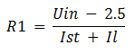
where Ist is the TL431 current and Il is the load current. The input current of the reference pin is not taken into account, since it is ~2 µA.
In the complete switching circuit, two more resistors are added to the TL431, but in this case, an arbitrary output voltage can be obtained.

The resistor values of the voltage divider and the output voltage of the TL431 are related as follows:

, where Uref = 2.5 V, Iref = 2 μA. These are typical values and they have a certain scatter (see datasheet).
Given the value of one of the resistors and the output voltage, the value of the second resistor can be calculated.

And knowing the output voltage and input current, you can calculate the value of the resistor R1:

, where Iin is the input current of the circuit, which is the sum of the operating current of the TL431, the voltage divider current and the load current.
If TL431 is used to obtain the reference voltage, then the resistors R2 and R3 must be taken with an accuracy of 1% from the E96 series.
Calculation of the voltage regulator on TL431

Initial data
Input voltage Uin = 9 V
Required output voltage Uout = 5 V
Load current Il = 10 mA
Datasheet data:
Ist = 1..100 mA
Iref = 2 uA
Uref = 2.495 V
Payment
We set the value of the resistor R2. The maximum value of this resistor is limited by the current Iref = 2 μA. If we take the value of the resistor R2 equal to units / tens of kOhm, then this will do. Let R2 = 10 kOhm.
Since the TL431 is used as a power supply, high accuracy is not needed here and the term Iref*R2 can be neglected.

The rounded value of R3 will be equal to 10 kΩ.
The voltage divider current is Uout/(R1+R2) = 5/20000 = 250 µA.
The TL431 current can be from 1 to 100 mA. If we take the current Ist > 2 mA, then the divider current can be neglected.
Then the input current will be equal to Iin = Ist + Il = 2 + 10 = 12 mA.
And the value R1 = (Uin - Uout) / Iin = (9 - 5) / 0.012 = 333 Ohm. Round up to 300.
The power dissipated by the resistor R1 is (9 - 5) * 0.012 = 0.05 W. On the other resistors, it will be even less.
R1 = 300 Ohm
R2 = 10 kOhm
R3 = 10 kOhm
Approximately so, without taking into account the nuances.
Load capacity
If you use TL431 and hang a capacitor at the output, then the microcircuit may "buzz". Instead of reducing the output noise, a periodic sawtooth signal of a few millivolts will appear at the cathode.

The load capacitance at which the TL431 behaves stably depends on the cathode current and output voltage. Possible capacitance values are shown in the picture from the datasheet. The stable areas are those outside the charts.
A lot has already been written about LEDs, now readers do not know how to properly power them so that they do not burn out ahead of time. Now I continue to rapidly replenish the section of power supplies, voltage stabilizers and current converters.
The top ten popular electronic components include the TL431 adjustable stabilizer and its brother, the TL494 PWM controller. In power supplies, it acts as a “programmable voltage reference source, the switching circuit is very simple. In switching power supplies on the TL431, feedback and reference voltage are sometimes implemented.
Get acquainted with the characteristics and datasheets of other ICs used for power supply,.

- 1. Specifications
- 2. TL431 wiring diagrams
- 3. Pinout TL431
- 4. Datasheet in Russian
- 5. Graphs of electrical characteristics
Specifications

It has received wide application due to the coolness of its technical characteristics and the stability of parameters at different temperatures. Partially, the functionality is similar to the well-known one, only it works at low current strength and is intended for adjustment. All features and typical switching circuits are indicated in the datasheet in Russian. The analogue of TL431 will be the domestic KR142EN19 and the imported K1156EP5, their parameters are very similar. I haven't seen any other analogues.
Main characteristics:
- output current up to 100mA;
- output voltage from 2.5 to 36V;
- power 0.2W;
- temperature range TL431C from 0° to 70°;
- for TL431A from -40° to +85°;
- price from 28 rubles for 1 piece.
Detailed characteristics and operating modes are indicated in the datasheet in Russian at the end of this page or you can download
 Example of use on the board
The stability of the parameters depends on the ambient temperature, it is very stable, there is little noise at the output and the voltage floats +/- 0.005V according to the datasheet. In addition to the household modification TL431C from 0° to 70°, a version with a wider temperature range TL431A from -40° to 85° is available. The option you choose depends on the purpose of the device. Analogues have completely different temperature parameters.
It is impossible to check the health of the microcircuit with a multimeter, since it consists of 10 transistors. To do this, it is necessary to assemble a test switching circuit, by which you can determine the degree of serviceability, the element does not always fail completely, it can simply burn out.
Wiring diagrams TL431

The operating characteristics of the stabilizer are set by two resistors. The options for using this microcircuit may be different, but it has received the maximum distribution in power supplies with adjustable and fixed voltage. It is often used in current stabilizers in USB chargers, industrial power supplies, printers and other household appliances.
TL431 is in almost any ATX power supply from a computer, you can borrow from it. Power elements with radiators, diode bridges are also there.

On this chip, many charger circuits for lithium batteries are implemented. Radio constructors are produced for self-assembly with their own hands. The number of application options is very large, good schemes can be found on foreign sites.


Pinout TL431

As practice shows, the TL431 pinout can be different, and depends on the manufacturer. The image shows the pinout from the Texas Instruments datasheet. If you remove it from some kind of finished board, then the pinout of the legs can be seen on the board itself.
Datasheet in Russian

Many radio amateurs do not know English and technical terms very well. I have a fairly good command of the language of the alleged enemy, but when developing, it still annoys me to constantly remember the translation of electrical terms into Russian. The translation of the TL431 datasheet into Russian was made by our colleague, whom we thank.


Nikolay Petrushov
TL431, what kind of "beast" is this?
Rice. one TL431.
The TL431 was created in the late 70s and is currently widely used in industry and in amateur radio activities.
But despite its considerable age, not all radio amateurs are closely familiar with this wonderful body and its capabilities.
In the proposed article, I will try to acquaint radio amateurs with this microcircuit.
To begin with, let's see what is inside it and turn to the documentation for the microcircuit, the "datasheet" (by the way, the analogues of this microcircuit are KA431, and our microcircuits KR142EN19A, K1156EP5x).
And inside it has a dozen transistors and only three outputs, so what is it?

Rice. 2 TL431 device.
It turns out everything is very simple. Inside is a conventional op amp (triangle in the block diagram) with an output transistor and a voltage reference.
Only here this circuit plays a slightly different role, namely, the role of a zener diode. It is also called "Controlled Zener Diode".
How does he work?
We look at the block diagram of the TL431 in Figure 2. From the diagram, it can be seen that the op-amp has a (very stable) built-in 2.5 volt reference voltage (small square) connected to the inverted input, one direct input (R), a transistor at the output of the op-amp, a collector ( K) and an emitter (A), which is combined with the power supply terminals of the amplifier and a protective diode against polarity reversal. The maximum load current of this transistor is up to 100 mA, the maximum voltage is up to 36 volts.
Rice. 3 Plinth TL431.
Now, using the example of a simple circuit shown in Figure 4, we will analyze how it all works.
We already know that inside the microcircuit there is a built-in reference voltage source - 2.5 volts. In the first releases of microcircuits, which were called TL430, the voltage of the built-in source was 3 volts, in later releases, it reaches 1.5 volts.
This means that in order for the output transistor to open, it is necessary to apply a voltage to the input (R) of the operational amplifier that is slightly higher than the reference 2.5 volts (the prefix "slightly" can be omitted, since the difference is several millivolts and in the future we will assume that a voltage equal to the reference must be applied to the input), then a voltage will appear at the output of the operational amplifier and the output transistor will open.
To put it simply, the TL431 is something like a field effect transistor (or just a transistor) that opens at a voltage of 2.5 volts (or more) applied to its input. The opening-closing threshold of the output transistor is very stable here due to the presence of a built-in stable reference voltage source.

Rice. 4 Schematic on TL431.
It can be seen from the circuit (Fig. 4) that a voltage divider from resistors R2 and R3 is connected to the input R of the TL431 microcircuit, the resistor R1 limits the LED current.
Since the divider resistors are the same (the power supply voltage is divided in half), the output transistor of the amplifier (TL-ki) will open when the power supply voltage is 5 volts or more (5/2 = 2.5). In this case, 2.5 volts will be supplied to the input R from the divider R2-R3.
That is, our LED will light up (the output transistor will open) when the power supply voltage is 5 volts or more. It will go out respectively when the source voltage is less than 5 volts.
If you increase the resistance of the resistor R3 in the arm of the divider, then it will be necessary to increase the voltage of the power source more than 5 volts, so that the voltage at the input R of the microcircuit supplied from the divider R2-R3 again reaches 2.5 volts and the output transistor TL opens -ki.
It turns out that if this voltage divider (R2-R3) is connected to the PSU output, and the TL cathode to the base or gate of the PSU control transistor, then by changing the divider arms, for example, by changing the value of R3, it will be possible to change the output voltage of this PSU, because in this case, the stabilization voltage of the TL-ki (opening voltage of the output transistor) will also change - that is, we will get a controlled zener diode.
Or if you choose a divider without changing it in the future, you can make the PSU output voltage strictly fixed at a certain value.
Output;- if the microcircuit is used as a zener diode (its main purpose), then by selecting the resistances of the divider R2-R3 we can make a zener diode with any stabilization voltage in the range of 2.5 - 36 volts (the maximum limitation according to the "datasheet").
Stabilization voltage of 2.5 volts - obtained without a divider, if the input of the TL-ki is connected to its cathode, that is, close conclusions 1 and 3.
Then more questions arise. Is it possible, for example, to replace the TL431 with a conventional opamp?
- It is possible, only if there is a desire to design, but it will be necessary to assemble your own 2.5 volt reference voltage source and supply power to the opamp separately from the output transistor, since the current of its consumption can open the actuator. In this case, you can make the reference voltage whatever you like (not necessarily 2.5 volts), then you will have to recalculate the resistance of the divider used in conjunction with the TL431, so that at a given PSU output voltage, the voltage supplied to the input of the microcircuit is equal to the reference.
One more question - is it possible to use the TL431 as an ordinary comparator and assemble on it, say, a thermostat, or something like that?
It is possible, but since it differs from a conventional comparator by the presence of a built-in reference voltage source, the circuit will be much simpler. For example this;

Rice. five Thermostat on TL431.
Here, the thermistor (thermistor) is a temperature sensor, and it reduces its resistance as the temperature rises, i.e. has a negative TCR (Temperature Coefficient of Resistance). PTC thermistors, i.e. whose resistance increases with increasing temperature - are called posistors.
In this thermostat, when the temperature exceeds the set level (regulated by a variable resistor), a relay or some actuator will work, and the contacts will turn off the load (heaters), or, for example, turn on the fans, depending on the task.
This circuit has a small hysteresis, and to increase it, it is necessary to introduce an OOS between pins 1-3, for example, a tuning resistor of 1.0 - 0.5 mOhm and select its value experimentally, depending on the required hysteresis.
If it is necessary for the actuator to operate when the temperature drops, then the sensor and regulators must be swapped, that is, the thermistor should be included in the upper shoulder, and the variable resistance with a resistor in the lower one.
And in conclusion, you can easily figure out how the TL431 chip works in the powerful power supply circuit for the transceiver, which is shown in Figure 6, and what role the resistors R8 and R9 play here, and how they are selected.
Rice. 6 Powerful power supply for 13 volts, 22 amps.