How to make a lighted landline telephone alarm. Mobile phone ringing indicator light. Telephone call indicator on thyristor and relay
Almost everyone has a mobile phone today. In some life moments you need to find out about the presence of an active mobile phone nearby, for example, during exams. Or notify a hard of hearing person about the arrival of an SMS. For these cases, we need a mobile phone ringing indicator. Such a detector can be easily assembled with your own hands based on a simple circuit, even with basic amateur radio skills.
The main highlight of this circuit is its application for cell phone signal detection. The mobile phone signal travels in the frequency range from 0.9 to 3 GHz. Schottky diodes have one interesting feature, which makes it possible to rectify low-frequency signals with low noise levels. When an inductor is placed near an RF signal source, it receives the signal through mutual induction. This signal is rectified by a Schottky diode and further along the chain it is amplified. After this, the signal is suitable for powering a light indicator, which in a particular design uses an LED. Below is a picture with circuit diagram simple indicator mobile phone ringing. The device is powered by 12 volts DC

Inductor L1 = 10 µH;
Resistors: R1 = 100 Ohm; R2 = 100 KOhm; R3 = 3 KOhm; R4 = 200 Ohm; R5 = 100 Ohm; R6 = 10 Ohm;
Capacitor C1 = 100 nF
Transistor Q1 = BC547
Operational amplifier IC1 = LM339
The input detection part of the circuit consists of a diode, inductor, capacitor and resistor. D1 type BAT54 performs the detector function and rectifies the signal AC low frequency. Capacitance C1 is used to filter AC noise. Resistance R1 is required as a load.
The second part of the design is the amplifier circuit, the basis of which bipolar transistor Q1 connected in a common emitter (CE) circuit. This chain is required to amplify a weak signal to the required level.
The signal is then sent to a comparator based on the LM339 operational amplifier. Its inverting input receives reference voltage through a voltage divider. Since the amplifier's output voltage is still quite low, the reference voltage is set to low level about 4 V. This can be achieved by selecting a 200 ohm resistor and a 330 ohm potentiometer to adjust the voltage. An output impedance of 10 ohms is used to limit the current.
The antenna is a segment copper wire about 15 cm long. The signal from it goes to capacitors C1 and C2. Then from their common point it goes to the inverting input of the op-amp type CA3130. The non-inverting input is connected to the divider on components R1, R2.
Border="0">
Capacitance C4 is a ceramic disk with leads 18 mm long and 7.5 mm apart. It forms a loop antenna for the frequency band on which cell phones operate. An op-amp with a MOSFET transistor at the input sets a high input impedance, high operating frequency and low input current. A 10mV signal at the input provides full swing-to-peak output voltage. Capacitance C4 paired with inductance generates the input current of the op-amp, which turns into the control output voltage of transistor VT1.
The glow of the LED in the emitter circuit of transistor VT1 indicates the presence of a switched-on mobile phone near the detector. At the same time, from the collector, through the separating capacitor C7, the signal is sent to pin 2 of DD1, thereby starting the operation of a multivibrator built on the NE555 timer. As a result, the buzzer connected to pin 3 of the NE555 timer emits beep.
One friend asked for a call from his elderly parents who, while watching TV, often missed landline phone, put a light bulb above the TV on the bell.
The requirements were as follows:
- The light bulb (LED) must be bright enough.
- It is advisable to transmit the signal wirelessly from another room.
- Get everything done cheaply and quickly.
For implementation, a transceiver with a remote control was found, which determined the further implementation.
PT2262/PT2272 (IC2262/72, SC2262/72) are encoder-decoder devices that are used in simple radio-controlled systems (for example, CAME barriers). This kit operates at a frequency of 315 MHz, there are exactly the same kits at 422 MHz. The codes on the receiver and transmitter are set by hardware jumpers. By default, all remote controls operate without jumpers on the same code. Here
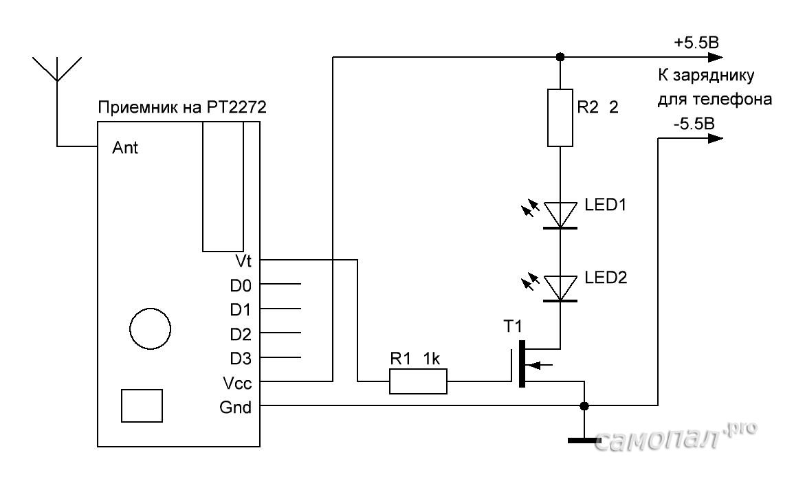
Receiver

The receiver is a PT2272 board. LEDs are connected to the output, triggered by all buttons on the remote control, via MOSFET IRF540. Resistance R2 is selected in such a way that when powered at 5.5V, the LEDs consume about 2W (current 400mA). To increase the sensitivity of the receiver, I soldered the antenna in the form of a 5cm piece of wire (1/16 wavelength - it no longer fits into the housing)

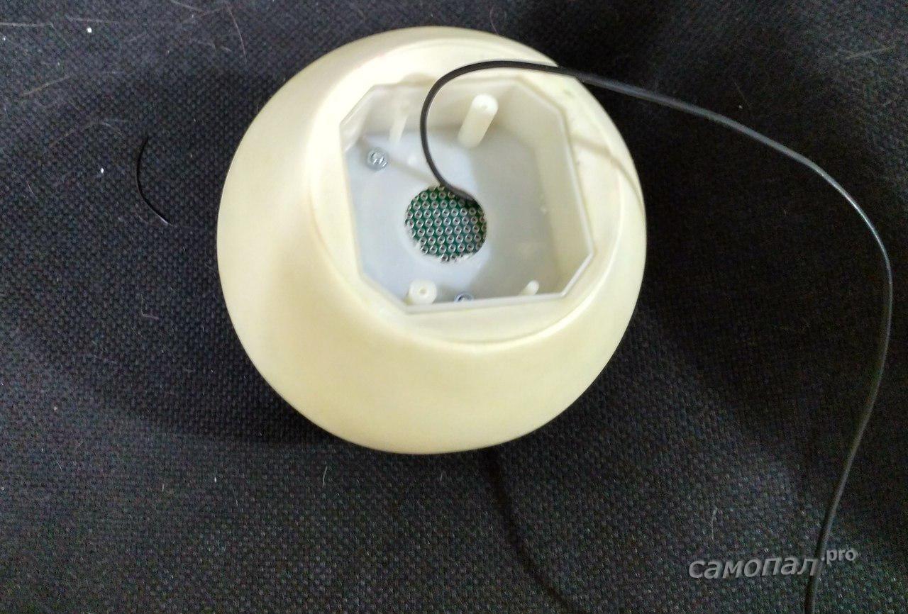
We put everything into the lamp body
Now, when you press any button on the remote control, the lamp flashes bright red. Testing showed reliable operation from different rooms of the apartment through brick walls.

Transmitter
We disassemble the key fob with the transmitter, remove the board

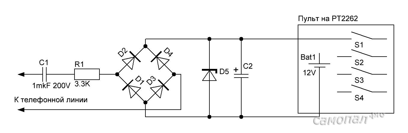
A circuit is connected to one of the remote control buttons on PT2262 that produces 5V when a call signal is received from the telephone line (~120V) / The capacitor is needed in order to eliminate the load in line standby mode (constant voltage). Otherwise, the telephone exchange may register the circuit as an off-hook signal and disconnect the line.
Now we put everything into the case.


Incoming call indicator light will be useful for people with hearing loss, as well as in any other cases when silence is necessary, for example, if someone is sleeping in the apartment small child. There are also the opposite situations - when the room is very noisy and the bell simply cannot be heard - various workshops, workshops, etc. Schemes are offered for both landline telephones and any mobile phone. Phone call indicator light can work instead phone call or simultaneously with it. The devices do not have such disadvantages as operation during a conversation and when dialing a number, consumption of electricity from the network in standby mode, and inconvenience of connecting to the line. The circuits are small and simple, can be built into the phone itself, do not consume energy in standby mode, and long-term operation of ring light indicator devices has shown their high reliability.
At the beginning there are several diagrams for indicating an incoming call for a landline phone.
First scheme connects in parallel with the telephone to the line anywhere and does not affect its operation due to the high input impedance.

When a ringing signal appears on the line, it is detected at element VD1 and supplied to a relay (reed switch) with an operating voltage of 27 V, for example RES55A RS4.569.601 (RS4.569.606) or RES55B RS4.569.626 (RS4.569.631), which turns on the thyristor when triggered VS1. The circuit can be further simplified if, instead of the VD2 diode bridge, one diode is used, connected to a thyristor in series with the load. Then the brightness of the lamp will decrease and become slightly pulsating (which is not significant), since it will only operate on one half-cycle of the mains voltage. The advantage is that in this mode the lamp will never burn out and the slightly flickering bell alarm attracts more attention. All elements of the circuit are placed on a single-sided printed circuit board with dimensions of 67x55 mm or can be connected by volumetric installation inside the telephone body. In this case, a simple switch S1 is installed on the case, and instead of capacitor C1, a capacitor available in the telephone set in the bell circuit can be used if its capacitance is at least 0.6 μF.

The design and printed circuit board of the first bell signaling light circuit.
Capacitors used in the device: C1 - MBM or similar for 160 V; C2 - K50-6 at 50 V. Diode matrix VD1 can be replaced with KTs405B, V, G, D. The use of other types of relays is unacceptable, since they can overload the telephone line when the call signal is active. If installed correctly, the device does not require configuration.
Second indicator light circuit assembled on a neon lamp (HL1), a transistor self-oscillator (VT1) and a triac switch (VS1). Feature neon lamp is the ability to pass current (when ignited) when the voltage across it exceeds 90 V, which allows it to be used as a threshold element. The call voltage amplitude on the telephone line exceeds this value. Other types can also be used as HL1, for example TN-0.5.

A self-oscillator is assembled on a unijunction transistor, generating short pulses to open a triac switch. If the polarity of the pulse coming to control VS1 is incorrect, the triac will not open (then when setting up, you need to swap the terminals on one of the T1 windings). Resistor R1 allows you to adjust the sensitivity of the indicator light so that it does not work when dialing a number. Topology printed circuit board for the diagram is given in the above file (zip 25Kb). The design uses the following parts: capacitor C1 type K52-1B, C2 type K10-17, resistor R1 type SP4-1, the rest - type C2-23-0.5. A triac can also be used with any other, less powerful one. Transformer T1 is wound with PELSHO-0.18 wire on a ferrite ring M4000NM1 of standard size K16x10x4 mm or ring M2000NM1 - K20x12x6 mm and contains 1 - 80 turns, 2-60 turns in the winding. Before winding, the sharp edges of the core must be rounded off with a file. Otherwise they will cut the wire. After winding and impregnating the coil with varnish, you must make sure that there is no leakage between the windings, as well as the windings and the ferrite of the frame. You can use any ready-made transformer with similar parameters.

The design and printed circuit board of the second bell light signaling circuit.
Another simpler, more reliable and cheaper one telephone call light signaling option, not requiring external power supply and even the body. The device consists of only one part - a neon indicator with a built-in resistor and threaded fastening (for example, N-803Y, N-804Y, N-808Y). The indicator is connected in parallel to the telephone set.
The principle of operation of the device is that at the moment of an incoming call, the voltage in the telephone line rises from 65 to 160 volts, which leads to the ignition of a neon lamp. The indicator does not disrupt the operation of the telephone network, because Thanks to the built-in resistor, the current through the indicator at the time of the call does not even exceed 1 mA.

The incoming call indicator can be installed directly in the telephone body. During installation, the phone should be disconnected from the network.
Unlike incandescent lamps, which have a resource of around 1000 hours, neon cold cathode lamps have a resource of at least 25,000 hours of continuous operation. It is worth noting that the operating mode of the incoming call indicator corresponds to frequent switching on and off, which significantly reduces the service life of incandescent lamps.
The following diagram is designed for light indication of an incoming call on any mobile phone.
The call is indicated regardless of whether the sound signal and vibration alert on the mobile phone are turned on or off. The device is compact, located next to the phone and is triggered by electromagnetic radiation that appears when the mobile phone receives a call.

R1- 100 kOhm R2 - 3.9 kOhm R3 - 1 MOhm
C1, C2 - 100N C3 - 220 x 25 V
D1 – indicator LED, better ultra-bright, D2 - 1N5819
Q1 - BC547
IC1 - 7555 or TS555CN timer
L1 – 10 µH
The electromagnetic field sensor is coil L1. The signal received by the coil is amplified by transistor Q1 and triggers a multivibrator assembled on a microcircuit integral timer IC1. Doubler AC voltage, assembled on a Schottke diode D2 and a capacitor C3, which is also a detector, produces a voltage of about 3 volts, which lights up the indicator LED D1.
Coil L1 is made on a mandrel with a diameter of 50 mm. and contains 150 turns of any enameled wire. After winding, the coil is removed, fastened with threads and placed inside the device along its perimeter.
Any integral timer with appropriate correction circuits, but it must be CMOS, otherwise it will not start from a 1.5 V supply. Any Schottke diode, for example, VAT46, can work in place of D2.
The device is powered autonomously from one 1.5 V cell, for example - one AA cell or even a disk battery from electronic watch and a calculator. A power switch is not provided, since all elements of the circuit operate in key mode and consume a current (in standby mode) of no more than 200 μA. If you wish, you can add. When installed correctly mobile phone ring light alarm device works immediately, does not require adjustment.
This circuit of the mobile phone ringer light indicator is intended to indicate to its owner that there is cell phone there was an incoming call. This is very convenient to use in situations where, due to strong background noise, it is impossible to hear the call, either in muted mode, or if the phone is not nearby, for example in a bag.
Description of the operation of the bell indicator light
When an incoming call arrives on a mobile phone, data is exchanged between the base station and the phone. The carrier frequency is about 900 MHz. Induction coil L1 picks up these oscillations, which are then sent to transistor Q1.
This transistor amplifies a weak signal and its pulses from the collector are sent to the input of Timer 55 is turned on in multivibrator mode, the operation of which is triggered by a signal at pin 2. As a result, rectangular pulses appear at output 3 of timer 555, as a result of which LED D2 begins to blink. Flashing LED indicates an incoming call.

Note
Coil L1 is wound on a mandrel with a diameter of 5 mm with enameled copper wire with a diameter of 0.2 mm, and contains 150 turns. You can also use a 10 µH inductive coil instead.
Light indication of incoming call
The call indicator light can work instead of a telephone call or simultaneously with it. The indicator will be useful for older people with hearing loss, and will also eliminate telephone calls at night. The device will be simply necessary if a small child sleeps in the apartment.
Here are three options for implementing such a device. All circuits do not consume energy in standby mode, do not operate when talking or dialing a number on a telephone, and long-term operation of the devices has shown their high reliability.
The circuit shown in Fig. 1 is connected to the telephone line anywhere in parallel with the telephone and does not affect its operation since it has a high input impedance. If there is a ringing signal in the line, the alternating voltage is rectified at element VD1 and supplied to a reed relay with an operating voltage of 27 V, which, when triggered, turns on the thyristor VS1.
Rice. 1
The circuit can be further simplified if, instead of the VD2 diode bridge, one diode is used, connected to the thyristor in series with the load. Then the brightness of the lamp will decrease and the glow will become slightly pulsating (which is not significant), since it will only work on one half-cycle of the mains voltage.
All elements of the circuit are placed on a single-sided printed circuit board (see Fig. 2) with dimensions of 67x55 mm or can be connected by volumetric mounting inside the telephone body. In this case, switch S1 is installed on the housing, and instead of capacitor C1, a capacitor available in the telephone set in the bell circuit can be used if its capacitance is at least 0.6 μF.

Rice. 2
Capacitors used in the device: C1 - MBM or similar for 160 V; C2 - K50-6 for 50 V. Diode matrix VD1 can be replaced with KTs405B, V, G, D. Relay with an operating voltage of 27 V type RES55A RS4.569.601 (RS4.569.606) or RES55B RS4.569.626 (RS4.569.631), The use of other types of relays is unacceptable, as they may overload the telephone line when the call signal is active. If installed correctly, the device does not require configuration.
The diagram shown in Fig. 3, assembled on a neon lamp (HL1), a transistor self-oscillator (VT1) and a triac switch (VS1).

Fig.3
A feature of a neon lamp is its ability to pass current (when it lights up) when the voltage across it exceeds 90 V, which allows it to be used as a threshold element. The call voltage amplitude on the telephone line exceeds this value. Other types can also be used as HL1, for example TN-0.5.
A self-oscillator is assembled on a unijunction transistor VT1, generating short pulses to open a triac switch. If the polarity of the pulse coming to control VS1 is incorrect, the triac will not open (when setting up, you will have to swap the pins on one of the T1 windings).
Resistor R1 allows you to adjust the sensitivity of the indicator light so that it does not work when dialing a number.
The PCB topology for the circuit is shown in Fig. 4.

Rice. 4
The design uses the following parts: capacitor C1 type K52-1B, C2 type K10-17, resistor R1 type SP4-1, the rest - type C2-23-0.5. A triac would be suitable for any other, less powerful one.
The diagram shown in Fig. 5 is similar in principle to the one described above, but it uses a zener diode VD2 as a threshold element, and in addition to the indicator light, it has a switchable sound alarm.

Rice. 5
The circuit is not critical to parts and does not require configuration if assembled correctly.
When connecting circuits to a 220 V network, it is advisable to observe the phasing shown in the diagram. This will eliminate the possibility of interference entering the TL (at the moment EL1 is turned on) through the decoupling pulse transformer T1.
Source of material: radioman.ru