Homemade sand moisture sensor. Corrosion-resistant soil moisture sensor, suitable for dacha automation. Why is this device needed?
You can often find devices on sale that are installed on a flower pot and monitor the level of soil moisture, turning on the pump if necessary and watering the plant. Thanks to this device, you can safely go on vacation for a week without fear that your favorite ficus will wither. However, the price of such devices is unreasonably high, because their design is extremely simple. So why buy if you can make it yourself?
Scheme
I propose for assembly a circuit diagram of a simple and proven soil moisture sensor, the diagram of which is shown below:Two metal rods are lowered into the bud of the pot, which can be done, for example, by bending a paper clip. They need to be stuck into the ground at a distance of about 2-3 centimeters from each other. When the soil is dry, it conducts poorly electric current, the resistance between the bars is very high. When the soil is wet, its electrical conductivity increases significantly and the resistance between the rods decreases; it is this phenomenon that underlies the operation of the circuit.
A 10 kOhm resistor and a section of soil between the rods form a voltage divider, the output of which is connected to the inverting input of the operational amplifier. Those. the voltage on it depends only on how moist the soil is. If you place the sensor in moist soil, the voltage at the op-amp input will be approximately 2-3 volts. As the soil dries out, this voltage will increase and reach a value of 9-10 volts when the soil is completely dry (specific voltage values depend on the type of soil). The voltage at the non-inverting input of the op-amp is set manually with a variable resistor (10 kOhm in the diagram, its value can be changed within 10-100 kOhm) in the range from 0 to 12 volts. Using this variable resistor, the sensor response threshold is set. The operational amplifier in this circuit works as a comparator, i.e. it compares the voltages at the inverting and non-inverting inputs. As soon as the voltage from the inverting input exceeds the voltage from the non-inverting input, a power supply minus appears at the output of the op-amp, the LED lights up and the transistor opens. The transistor in turn activates a relay that controls the water pump or electric valve. Water will begin to flow into the pot, the soil will become moist again, its electrical conductivity will increase, and the circuit will turn off the water supply.
PCB, proposed for the article, is designed for the use of a dual operational amplifier, for example, TL072, RC4558, NE5532 or other analogues, one half of it is not used. The transistor in the circuit is used with low or medium power and PNP structure; for example, KT814 can be used. Its task is to turn the relay on and off; also, instead of a relay, you can use a key on field effect transistor like I did. The supply voltage of the circuit is 12 volts.
Download the board:
(downloads: 330)
Soil Moisture Sensor Assembly
It may happen that when the soil dries out, the relay does not turn on clearly, but first begins to click quickly, and only after that it is set in the open state. This suggests that the wires from the board to the plant pot are picking up network noise, which has a detrimental effect on the operation of the circuit. In this case, it wouldn’t hurt to replace the wires with shielded ones and install electrolytic capacitor a capacitance of 4.7 - 10 µF parallel to the soil area, in addition to the 100 nF capacitance indicated in the diagram.I really liked the work of the scheme, I recommend repeating it. Photo of the device I assembled:
Homemade, stable sensor soil moisture for automatic irrigation system
This article arose in connection with the construction of an automatic watering machine for caring for indoor plants. I think that the watering machine itself may be of interest to the DIYer, but now we will talk about the soil moisture sensor. https://site/
The most interesting videos on Youtube
 |
 |
 |
 |
Prologue.
Of course, before reinventing the wheel, I surfed the Internet.
Humidity sensors industrial production turned out to be too expensive, and I never managed to find detailed description at least one such sensor. The fashion for trading “pig in pokes”, which came to us from the West, seems to have already become the norm.
Although there are descriptions of homemade amateur sensors on the network, they all work on the principle of measuring soil resistance to direct current. And the very first experiments showed the complete failure of such developments.
Actually, this didn’t really surprise me, since I still remember how, as a child, I tried to measure the resistance of the soil and discovered... an electric current in it. That is, the microammeter needle recorded the current flowing between two electrodes stuck into the ground.
Experiments that took a whole week showed that soil resistance can change quite quickly, and it can periodically increase and then decrease, and the period of these fluctuations can be from several hours to tens of seconds. In addition, in different flower pots, soil resistance changes differently. As it turned out later, the wife selects an individual soil composition for each plant.
At first, I completely abandoned measuring soil resistance and even began to build an induction sensor, since I found an industrial humidity sensor on the Internet, about which it was written that it was induction. I was going to compare the frequency of the reference oscillator with the frequency of another oscillator, the coil of which is placed on a pot with a plant. But when I started prototyping the device, I suddenly remembered how I once came under “step voltage”. This prompted me to do another experiment.

And indeed, in all the homemade structures found on the network, it was proposed to measure the soil resistance to direct current. What if you try to measure the resistance alternating current? After all, in theory, then the flowerpot should not turn into a “battery”.
Collected the simplest scheme and immediately tested it on different soils. The result was encouraging. No suspicious tendencies towards increasing or decreasing resistance were detected even within several days. Subsequently, this assumption was confirmed on an operating irrigation machine, the operation of which was based on a similar principle.
Electrical circuit of a soil moisture threshold sensor.
As a result of research, this circuit appeared on one single chip. Any of the listed microcircuits will do: K176LE5, K561LE5 or CD4001A. We sell these microcircuits for only 6 cents.
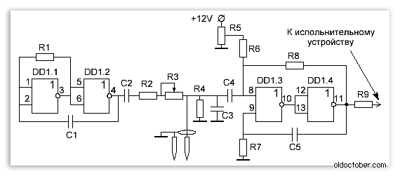
The soil moisture sensor is a threshold device that responds to changes in resistance to alternating current (short pulses).
A master oscillator is assembled on elements DD1.1 and DD1.2, generating pulses at intervals of about 10 seconds. https://site/
Separating capacitors C2 and C4. They do not allow direct current generated by the soil into the measuring circuit.
Resistor R3 sets the response threshold, and resistor R8 provides hysteresis of the amplifier. Trimmer resistor R5 sets the initial bias at input DD1.3.
Capacitor C3 is noise-protecting, and resistor R4 determines the maximum input impedance measuring circuit. Both of these elements reduce the sensitivity of the sensor, but their absence can lead to false alarms.
You should also not choose a microcircuit supply voltage lower than 12 Volts, as this reduces the real sensitivity of the device due to a decrease in the signal-to-noise ratio.
Attention!
I don't know if prolonged exposure to electrical pulses can have harmful effects on plants. This scheme was used only at the stage of development of the irrigation machine.
To water the plants, I used a different circuit, which generates only one short measuring pulse per day, timed to coincide with the time of watering the plants.
Arduino Soil Moisture Sensor designed to determine the moisture content of the soil in which it is immersed. It allows you to find out about insufficient or excessive watering of your household or garden plants. Connecting this module to the controller allows you to automate the process of watering your plants, garden or plantation (a kind of “smart watering”).The module consists of two parts: a YL-69 contact probe and a YL-38 sensor, wires for connection are included. A small voltage is created between the two electrodes of the YL-69 probe. If the soil is dry, the resistance is high and the current will be less. If the ground is wet, the resistance is less, the current is a little more. Based on the final analog signal, you can judge the degree of humidity. The YL-69 probe is connected to the YL-38 sensor via two wires. In addition to the contacts for connecting to the probe, the YL-38 sensor has four contacts for connecting to the controller.
- Vcc – sensor power supply;
- GND – ground;
- A0 - analog value;
- D0 – digital value of the humidity level.
Module Specifications
- Supply voltage: 3.3-5 V;
- Current consumption 35 mA;
- Output: digital and analog;
- Module size: 16×30 mm;
- Probe size: 20×60 mm;
- Total weight: 7.5 g.
Usage example
Let's consider connecting a soil moisture sensor to Arduino. Let's create a project for soil moisture level indicator for indoor plant(your favorite flower that you sometimes forget to water). To indicate the level of soil moisture we will use 8 LEDs. For the project we will need the following parts:- Arduino Uno board
- Soil moisture sensor
- 8 LEDs
- Development board
- Connecting wires.

Let's launch the Arduino IDE. Let's create a new sketch and add the following lines to it: // Soil moisture sensor // http://site // contact for connecting the analog output of the sensor int aPin=A0; // contacts for connecting indication LEDs int ledPins=(4,5,6,7,8,9,10,11); // variable to save the sensor value int avalue=0; // variable for the number of glowing LEDs int counted=8; // value of full watering int minvalue=220; // critical dryness value int maxvalue=600; void setup() ( // initializing the serial port Serial.begin(9600); // setting up the LED indication pins // to OUTPUT mode for(int i=0;i<8;i++) { pinMode(ledPins[i],OUTPUT); } } void loop() { // получение значения с аналогового вывода датчика avalue=analogRead(aPin); // вывод значения в монитор последовательного порта Arduino Serial.print("avalue=";Serial.println(avalue); // scale the value by 8 LEDs counted=map(avalue,maxvalue,minvalue,0.7); // indication of the humidity level for(int i=0;i<8;i++) ( if(i<=countled) digitalWrite(ledPins[i],HIGH); //light the LED else digitalWrite(ledPins[i],LOW) ; // turn off the LED ) // pause before the next value is received 1000 ms delay(1000); ) The analog output of the sensor is connected to the analog input of the Arduino, which is an analog-to-digital converter (ADC) with a resolution of 10 bits, which allows the output to obtain values from 0 to 1023. The value of the variables for complete watering (minvalue) and severe dry soil (maxvalue ) we obtain experimentally. Greater soil dryness corresponds to a larger analog signal value. Using the map function, we scale the analog value of the sensor to the value of our LED indicator. The higher the soil moisture, the higher the LED indicator value (number of lit LEDs). By connecting this indicator to a flower, we can see the degree of humidity on the indicator from a distance and determine the need for watering.
Frequently asked questions FAQ
1. Power LED does not light up- Check the presence and polarity of the power supplied to the YL-38 sensor (3.3 - 5 V).
- Adjust the response threshold using the potentiometer. Check the connection of the YL-38 sensor with the YL-69 probe.
- Check the connection of the YL-38 sensor with the YL-69 probe.
- Check for the presence of a probe in the ground.
This simple homemade device is used for water or other liquid, in various rooms or containers. For example, these sensors are very often used to detect possible flooding of the basement or cellar with melt water or in the kitchen under the sink, etc.
The role of the humidity sensor is performed by a piece of foil fiberglass with grooves cut into it, and as soon as water gets into them, the machine will disconnect the load from the network. Or if we use the rear contacts, the automatic relay will turn on the pump or the device we need.

We manufacture the sensor itself in exactly the same way as in the previous diagram. If liquid gets on the contacts of the F1 sensor, the sound alarm will begin to emit a constant sound signal, and the HL1 LED will also light up.

Using the SA1 toggle switch, you can change the order of the HL1 indication to a continuous LED glow in standby mode.
This humidity sensor circuit can be used as a rain detector, overflow of a liquid container, water leakage, etc. The circuit can be powered from any five-volt DC power source.

The source of the sound signal is a sound emitter with a built-in sound generator. The humidity sensor is made from a strip of foil PCB with a thin track in the foil. If the sensor is dry, the sound signal does not signal. If the sensor gets wet, we will immediately hear an intermittent alarm signal.
The design is powered by a Krona battery and will last for two years, because during standby mode, the circuit consumes almost zero current. Another bonus of the circuit is the fact that almost any number of sensors can be connected parallel to the input and thus cover the entire controlled area at a time. The detector circuit is built on two 2N2222 type transistors connected in a Darlington manner."
List of radio componentsR1, R3 - 470K
SW1 - button
R2 - 15k
SW2 - switch
R4 - 22K
B1 - crown type battery
C1 - capacitor with a capacity of 0.022 µF
T1, T2 - input terminals
PB1 - (RS273-059) piezo buzzer
Q1, Q2 - 2N2222 type transistors
When the first transistor opens, it immediately unlocks the second, which turns on the piezo buzzer. In the absence of liquid, both transistors are securely off and very low current is consumed from the battery. When the buzzer is turned on, the current consumption increases to 5 mA. Sound emitters of type RS273-059 have a built-in generator. If a more powerful alarm is needed, connect several buzzers in parallel or use two batteries.

We manufacture printed circuit boards with dimensions of 3*5 cm.
The test toggle switch connects a 470 kOhm resistance to the input, simulating the action of a liquid, thereby checking the functionality of the circuit. Transistors can be replaced with domestic ones, such as KT315 or KT3102.

An automatic humidity sensor is designed to turn on forced ventilation of a room at high air humidity; it can be installed in the kitchen, bathroom, cellar, basement, garage. Its purpose is to turn on the fans for forced ventilation of the room when the humidity in it approaches 95... 100%.
The device is highly economical, reliable, and its simplicity of design makes it easy to modify its components to suit specific operating conditions. The diagram of the humidity sensor is shown in the figure below.

The scheme works as follows. When the air humidity in the room is normal, the resistance of the dew sensor - gas resistor B1 does not exceed 3 kOhm, transistor VT2 is open, the powerful high-voltage field-effect transistor VT1 is closed, the primary winding of transformer T1 is de-energized. The load connected to the XP1 connector will also be de-energized.
As soon as the air humidity approaches the point of dew, for example, it boils when left unattended, the bathroom is filled with hot water, the cellar is flooded with melted water, groundwater, the thermostat of the water heater has failed, the resistance of the gas resistor B1, the sharp alternating current is removed from the secondary winding T1 and supplied to the bridge diode rectifier VD2. Rectified voltage ripples are smoothed out by a high-capacity oxide capacitor C2. The parametric DC voltage stabilizer is built on a composite transistor VT3 with a high base current transfer coefficient of the KT829B type, a zener diode VD5 and a ballast resistor R6.
Capacitors SZ, C4 reduce output voltage ripple. Fans with an operating voltage of 12...15V, for example, “computer” fans, can be connected to the output of the voltage stabilizer. Fans with a total power of up to 100 W, designed for a supply voltage of 220 VAC, can be connected to the XP1 socket. A bridge rectifier VD1 is installed in the open supply circuit of the step-down transformer T1 and the high-voltage load. A pulsating DC voltage is supplied to the drain of the field-effect transistor. The cascade on transistors VT1, VT2 is powered by a stabilized voltage of +11 V, set by the zener diode VD7. The voltage is supplied to this zener diode through the chain R2, R3, VD4, HL2. This circuit design allows the field-effect transistor to be opened completely, which significantly reduces the power dissipated on it.
Transistors VT1, VT2 are included as a Schmitt trigger, which prevents the field-effect transistor from being in an intermediate state, which prevents it from overheating. The sensitivity of the humidity sensor is set by trimming resistor R8, and, if necessary, by selecting the resistance of resistor R7. Varistors RU1 and RU2 protect device elements from damage by network voltage surges. The green LED HL2 indicates the presence of supply voltage, and the red LED HL1 signals high humidity and the device is switched to forced ventilation mode.
You can connect up to 8 low-voltage fans with a current consumption of up to 0.25 A each to the device and, or several fans with a supply voltage of 220 V. If using this device it is necessary to control a more powerful load with a supply voltage of 220 V, then to the output voltage stabilizer, you can connect electromagnetic relays, for example, type G2R-14-130, the contacts of which are designed for switching alternating current up to 10 A at a voltage of 250 V. In parallel with resistor R8, you can install a thermistor with negative TCR, resistance 3.3...4, 7 kOhm at 25°C, placed, for example, above a gas or electric stove, which will allow you to turn on the ventilation also when the air temperature rises above 45...50 °C, when the stove burners are operating at full power.
In place of transformer T1, you can install any step-down transformer with an overall power of at least 40 W, the secondary winding of which is designed for a current value not less than the current of the low-voltage load. Without rewinding the secondary winding “Yunost”, “Sapphire”. Unified transformers TPP40 or TN46-127/220-50 are also suitable. When making a transformer yourself, you can use an W-shaped magnetic core with a cross-section of 8.6 cm2. The primary winding contains 1330 turns of wire with a diameter of 0.27 mm.
Secondary winding 110 turns of winding wire with a diameter of 0.9 mm. Instead of the KT829B transistor, any of the KT829, KT827, BDW93C, 2SD1889, 2SD1414 series will do. This transistor is installed on a heat sink, the size of which will depend on the load current and the magnitude of the collector-emitter voltage drop VT3. It is advisable to choose a heat sink with which the temperature of the VT3 transistor body would not exceed 60°C.
If the voltage on the plates of capacitor C2 with a load connected to the output of the stabilizer is more than 20 V, then to reduce the power dissipated by VT3, you can unwind several turns from the secondary winding of the transformer. The field effect transistor IRF830 can be replaced with KP707V2, IRF422, IRF430, BUZ90A, BUZ216. When installing this transistor, it must be protected from breakdown by static electricity. Instead of SS9014, you can use any of the KT315, KT342, KT3102, KT645, 2SC1815 series. When replacing bipolar transistors, take into account the differences in pinouts.
KBU diode bridges can be replaced with similar ones KVR08, BR36, RS405, KBL06. Instead of 1N4006, you can use 1N4004 - 1N4007, KD243G, KD247V, KD105V. Zener diodes: 1N5352 - KS508B, KS515A, KS215Zh; 1N4737A - KS175A, KS175Zh, 2S483B; 1 N4741A - D814G, D814G1, 2S211ZH, KS221V.
LEDs can be of any general use, for example, AL307, KIPD40, L-63 series. Oxide capacitors are imported analogs of K50-35, K50-68. Varistors - any low or medium power for a classified operating voltage of 430 V, 470 V, for example, FNR-14K431, FNR-10K471. The gas resistor GZR-2B, sensitive to air humidity, was taken from an old domestic video recorder “Electronics VM-12”. A similar gas resistor can be found in other faulty domestic and imported VCRs or in old cassette video cameras. This gas resistor is usually bolted to the metal chassis of the tape drive. Its purpose is to block the operation of the device when the tape mechanism fogs up, which prevents the magnetic tape from wrapping and damaging. The device can be mounted on a printed circuit board measuring 105x60 mm. It is preferable to place the gas resistor in a separate box made of insulating material with holes, installed in a cooler place. It is also recommended to screw it to a small metal plate, perhaps through a thin mica insulating spacer. To protect the mounted board from moisture, the mounting and printed conductors are coated with several layers of FL-98, ML-92 varnish or tsaponlac.
There is no need to paint over the gas resistor. To check the device’s functionality, you can simply exhale air from your lungs onto the gas resistor or bring a container of boiling water closer. After a few seconds, the HL1 LED will flash and the fans connected as loads will begin to fight the increased humidity. In standby mode, the device consumes current from the network about 3 mA, which is very little. Since the device consumes less than 1 W of power in standby mode, it can be operated around the clock without worrying about power consumption. Since the device is partially galvanically connected to the 220 V AC mains voltage, appropriate precautions should be taken when setting up and operating the device.
As a result of numerous experiments, this soil sensor circuit appeared on one single chip. Any of the microcircuits will do: K176LE5, K561LE5 or CD4001A.
The air humidity sensor, the diagram and drawings of which are attached, makes it possible to fully automate the process of monitoring and managing the relative humidity of the air in any room. This humidity sensor circuit makes it possible to measure relative humidity in the range from 0–100%. With very high accuracy and stability of parameters
Light and sound alarm for water boiling. - Radio, 2004, No. 12, pp. 42, 43.
. - Circuitry, 2004, No. 4, pp. 30-31.
Constant" in the cellar. - CAM, 2005, No. 5, pp. 30, 31.
The poet Andrei Voznesensky once said: “laziness is the engine of progress.” It is perhaps difficult to disagree with this phrase, because most electronic devices are created precisely for the purpose of making our daily lives easier, full of worries and all sorts of hectic affairs.
If you are reading this article now, then you are probably very tired of the process of watering flowers. After all, flowers are delicate creatures, you overwater them a little, you’re unhappy, you forget to water them for a day, that’s it, they’re about to fade. And how many flowers in the world have died just because their owners went on vacation for a week, leaving the poor green creatures to wither in a dry pot! It's scary to imagine.
It is to prevent such terrible situations that automatic watering systems were invented. A sensor is installed on the pot that measures soil moisture - it consists of stainless steel metal rods stuck into the ground at a distance of a centimeter from each other.
They are connected via wires to a circuit whose task is to open the relay only when the humidity drops below the set value and close the relay at the moment when the soil is saturated with moisture again. The relay, in turn, controls the pump, which pumps water from the reservoir directly to the root of the plant.
Sensor circuit


As is known, the electrical conductivity of dry and wet soil differs quite significantly; it is this fact that underlies the operation of the sensor. A 10 kOhm resistor and a section of soil between the rods form a voltage divider; their midpoint is connected directly to the input of the op-amp. The voltage is supplied to the other input of the op-amp from the midpoint of the variable resistor, i.e. it can be adjusted from zero to supply voltage. With its help, the switching threshold of the comparator, in the role of which the op-amp operates, is set. As soon as the voltage at one of its inputs exceeds the voltage at the other, the output will be logical “1”, the LED will light up, the transistor will open and turn on the relay. You can use any transistor, PNP structure, suitable for current and voltage, for example, KT3107 or KT814. Operational amplifier TL072 or any similar one, for example RC4558. A low-power diode, for example, 1n4148, should be placed in parallel with the relay winding. The supply voltage of the circuit is 12 volts.


Due to the long wires from the pot to the board itself, a situation may arise that the relay does not switch clearly, but begins to click at the frequency of the alternating current in the network, and only after some time is set in the open position. To eliminate this bad phenomenon, you should place an electrolytic capacitor with a capacity of 10-100 μF in parallel with the sensor. Archive with the board. Happy building! Author - Dmitry S.
Discuss the article SOIL MOISTURE SENSOR DIAGRAM