How to dimension circles in a drawing. General rules for dimensioning drawings
All images are accompanied by drawing dimensions. When applying dimensions, one should be guided by the main provisions of GOST 2.307-2011 "Dimensioning and limit deviations".
The basis for determining the size of the depicted product and its elements are the dimensional numbers indicated in the graphic document. The numerical value of the size to be entered must correspond to its natural value (actual value), regardless of the accepted scale of the image. On the training drawings, only the nominal values \u200b\u200bof dimensions are applied without indicating their maximum deviations.
Linear dimensions are indicated on the drawing in millimeters without indicating the unit of measurement, angular dimensions - in degrees, minutes.
Dimensions in graphic documents are indicated by dimensional numbers and dimension lines.
When applying the size of a straight segment, the dimension line is drawn parallel to this segment, the extension lines are perpendicular to the dimension lines (Fig. 7).
Rice. 7. Rules for setting dimensions on the drawing
Dimension lines are preferably drawn outside the outline of the image. It is not allowed to use contour lines, axial, center and extension lines as dimension lines. It is necessary to avoid the intersection of dimension and extension lines. The dimension line at both ends is limited by arrows resting on the extension lines. The shape of the arrow and the approximate ratio of the sizes of its elements are shown in fig. eight.
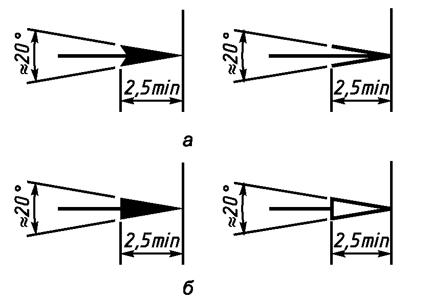
Rice. 8. The image of the arrows in the drawing
Extension lines are drawn from the lines of the visible contour. The extension lines should extend beyond the ends of the arrows of the dimension line by 1 ... 5 mm.
The distance between the contour line and the dimension line is selected depending on the size of the image and the saturation of the drawing. The minimum distance between the dimension line and the contour line should be 10 mm, and the minimum distance between parallel dimension lines should be 7 mm.
Dimensional numbers are applied above the dimension line as close as possible to its middle. When applying several parallel dimension lines, the dimension numbers should be staggered (Fig. 7).
If there is not enough space for drawing arrows and dimensional numbers, then they are applied using one of the methods shown in Fig. 9. If there is not enough space for arrows on dimension lines located in a chain, it is allowed to replace the arrows with serifs 1-3 mm long, applied at an angle of 45 ° to the dimension lines or clearly marked points (Fig. 9). If there is not enough space for an arrow due to a closely spaced contour or extension line, the latter can be interrupted.

Rice. 9. Dimension lines
Dimensional numbers are not allowed to be divided or crossed by any lines of the drawing. In the place where the dimension number is applied, the axial, center lines and hatching lines are interrupted (Fig. 10).

Dimensions related to the same structural element (groove, protrusion, hole, etc.) are recommended to be grouped in one place, placing them on the image in which the geometric shape of this element is shown most fully (Fig. 11).

Rice. 11. Size grouping
When drawing the size of the arcs, indicate its radius, for a circle - the diameter. A capital letter is placed before the radius number. latin letter « R» , (for example, R20 ), before the dimension number of the diameter - the sign "" (for example, 20 ).
In the case of making an image of a part with a spherical surface, if it is difficult to distinguish it from other surfaces, it is allowed to apply the word “Sphere” or the sign “” when applying the size of the diameter (radius), sphere (for example, SphereR15 or 40 ).
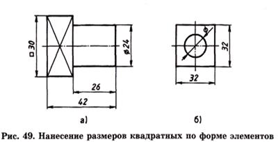
The square in the drawing is determined by two sizes of its sides or one size with the sign "" (Fig. 12). Diagonals on the edge of the element, drawn by thin lines, conditionally designate a plane.
The dimensions of the chamfers at an angle of 45º are applied as shown in Figure 12 a. The chamfer width and angle are combined into one dimension using the "×" sign.
The dimensions of the chamfers at other angles are indicated separately by linear and angular dimensions (in Fig. 12 a so the chamfer dimensions are indicated at an angle of 30º with a chamfer width of 3 mm) or two linear dimensions (Fig. 12 b).
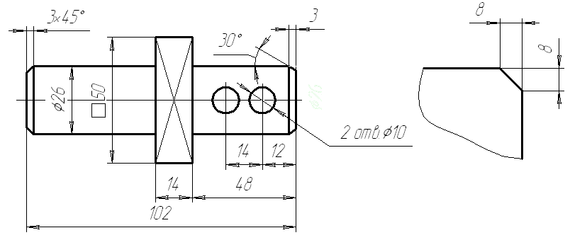
Rice. 12 a Rice. 12 b
If a view or section of a symmetrical object or individual symmetrically located elements is depicted only up to the axis of symmetry or with a break, then the dimension lines related to these elements are drawn with a break, and the break of the dimension line is made further than the axis or break line of the object (Fig. 13).

Rice. 13. Dimensioning with a break
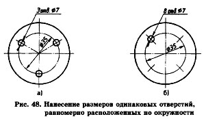
Total dimensions should be minimal, but sufficient for the manufacture and control of the product. The dimensions of the same element in the drawing are not allowed to be repeated. The dimensions of several identical elements of the product, as a rule, are applied once with an indication of the number of these elements on the shelf of the leader line or under it (Fig. 14). At the same time, for elements evenly spaced around the circumference (for example, holes), the angular dimensions between them are not set, provided that one of these elements lies on one of the axes of symmetry (Fig. 14 a). Only the size of the diameter of the circle on which the centers of the holes are located in fig. fourteen a. If none of the holes lies on the axis of symmetry, then you should set the angle to the first element (Fig. 14 b).

Rice. fourteen a Rice. fourteen b
The standard (GOST 2.307-68) establishes the rules for applying dimensions to drawings.
The linear dimensions on the drawings are given in millimeters without designation of units of measure (mm). With other units of measurement (centimeters, meters), dimensional numbers are written with the designation of units of measurement (cm, mi). Angular dimensions are indicated in degrees, minutes, seconds with the designation of units of measurement. The total number of dimensions on the drawings should be minimal, but sufficient for the manufacture and control of the product.
There are strictly certain rules sizing. When applying the size of a straight segment, the dimension line is drawn parallel to this segment, and the extension lines are perpendicular to the dimension lines (Fig. 40, b). The extension lines go beyond the dimensional ones by 1-3 mm. The distance from the dimension line to the image outline must be at least 10 mm, and the distance between two nearby dimension lines must be at least 7 mm (Fig. 40, b).
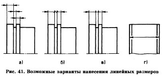
Arrows are drawn at the ends of the dimension lines. The shape and dimensions of the arrow are shown in fig. 40 a. The size of the arrows must be the same throughout the drawing. Arrows with a lack of space can be replaced by serifs or dots (Fig. 41, b, c). It is allowed to put down the dimensions as shown in Fig. 41, city

Dimensional numbers are applied above the dimension line closer to the middle (Fig. 42).
When applying several parallel or concentric dimension lines, the dimension numbers above them are staggered (Fig. 43).
In the drawings, it is necessary to avoid the intersection of dimension and extension lines. If there is not enough space above the dimension line to apply the dimension number, then the dimensions are affixed as shown in Fig. 44.

In places where the dimension number is applied, the axial, center lines and hatching lines are interrupted (Fig. 45, a, b).
When drawing the dimensions of the arcs, a radius sign - R is placed in front of the dimension number. The height of the radius sign and the dimension number should be the same (Fig. 46, a).
When drawing several radii from one center, the dimension lines of any two radii are not located on the same straight line (Fig. 46, b). At big size radius center is allowed to approach the arc. In such cases, the dimension line is shown with a break (Fig. 46, c).
When drawing the dimensions of circles, a diameter sign is placed in front of the dimension number - 0 (Fig. 47).
If there is not enough space on the drawing, the dimensions of the diameter are affixed as shown in Fig. 47b.

The dimensions of several identical elements of the product are applied once, indicating their number on the leader shelf, fig. 48.
The dimensions of a square or square hole are plotted as shown in fig. 49.
The thickness of a flat part is indicated by the letter S followed by a dimension number (Fig. 50).

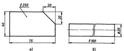
The length of the product is indicated by a small letter Latin alphabet- I (Fig. 51).
The application of the dimensions of the chamfer - the beveled edge of the rod, bar, hole - is carried out either by setting two linear dimensions (Fig. 52, b), or linear and angular dimensions(Fig. 52, c, d).
If there are several identical chamfers in the drawing, then the size is applied once as shown in fig. 52, c. This inscription means that two chamfers of 2 mm in size were removed at an angle of 45 °.
On the drawings it is necessary to put down the overall dimensions.
Overall dimensions are called dimensions that determine the limiting values \u200b\u200bof the external outlines of products. The overall dimensions include the dimensions of the length, width, height of the product.
dimensions there are always more than others, so they are placed farther from the image in the drawing than the rest.
On fig. 53 (roller) - dimensions are 75 mm and 40 mm.
On fig. 53 (half-cylinder) - the overall dimensions are 80 mm, 50 mm.

Reference dimensions are sometimes applied to the drawings. Dimensions applied on the drawing, but not subject to control, are called reference. In the drawing, they are marked with * (Fig. 54). At the location technical requirements(above the main inscription) make an entry: * - size for reference.
QUESTIONS AND TASKS
1. In what units is expressed linear dimensions on engineering drawings?
2. How many millimeters should the extension lines protrude beyond the ends of the arrows of the dimension lines?
3. What is the minimum distance between parallel dimension lines?
4. What signs indicate the thickness and length of the product?
5. What dimensions are called overall?
6. What sign indicates the dimensions for reference?
7. On an A4 sheet, draw an oil filter gasket (Fig. 55). Start by determining the location of the image on the drawing field. Then apply dash-dotted axial and center. Lead all constructions from them. Work with thin lines followed by a stroke. Apply dimensions.

The dimensions in the drawings are given in millimeters without the designation of units of measure (mm). With other units of measurement (centimeters, meters), dimensional numbers are written with the designation of units of measurement (cm, m). Angular dimensions are indicated in degrees, minutes, seconds with the designation of units of measurement. The total number of dimensions in the drawings should be minimal, but sufficient for the manufacture and control of the product.
There are strictly defined rules for sizing. When applying the size of a straight segment, the dimension line is drawn parallel to this segment, and the extension lines are perpendicular to the dimension lines (Fig. 40, b). The extension lines go beyond the dimensional ones by 1-3 mm. The distance from the dimension line to the image outline must be at least 10 mm, and the distance between two nearby dimension lines must be at least 7 mm (Fig. 40, b).
Arrows are drawn at the ends of the dimension lines. The shape and dimensions of the arrow are shown in fig. 40 a. The size of the arrows must be the same throughout the drawing. Arrows with a lack of space can be replaced by serifs or dots (Fig. 41, b, c). It is allowed to put down the dimensions as shown in Fig. 41, city
Dimensional numbers are applied above the dimension line closer to the middle (Fig. 42).
When applying several parallel or concentric dimension lines, the dimension numbers above them are staggered (Fig. 43).
In the drawings, it is necessary to avoid the intersection of dimension and extension lines. If there is not enough space above the dimension line to apply the dimension number, then they are affixed as shown in Fig. 44.


In places where the dimension number is applied, the axial, center lines and hatching lines are interrupted (Fig. 45, a, b). When drawing the dimensions of the arcs, the radius sign - R is placed in front of the dimension number. a). When drawing several radii from one center, the dimension lines of any two radii are not located on the same straight line (Fig. 46, b). With a large radius, the center can be brought closer to the arc. In such cases, the dimension line is shown with a break (Fig. 46, c).
When drawing the dimensions of circles, a diameter sign is placed in front of the dimension number (Fig. 47). If there is not enough space on the drawing, the dimensions of the diameter are affixed as shown in Fig. 47b.
The dimensions of several identical elements of the product are applied once, indicating their number on the leader shelf, fig. 48. The dimensions of a square or square hole are applied as shown in fig. 49.

![]()
The overall dimensions are always larger than others, so they are placed farther from the image in the drawing than the rest.
On fig. 53, a - overall dimensions 52 mm, 30 mm, 15 mm.
On fig. 53, b - overall dimensions are 75 mm and 40 mm.
On fig. 53, c - overall dimensions are 80 mm, 50 mm.
Reference is sometimes applied to the drawings. Dimensions applied on the drawing, but not subject to control, are called reference. In the drawing, they are marked with * (Fig. 54). At the location of the technical requirements (above the main inscription) make an entry: * - size for reference.
Questions and tasks
1. In what units are linear dimensions expressed on engineering drawings?
2. How many millimeters should the extension lines protrude beyond the ends of the arrows of the dimension lines?
3. What is the minimum distance between parallel dimension lines?
4. What signs indicate the thickness and length of the product?
5. What dimensions are called overall?
6. What sign indicates the dimensions for reference?
7. On an A4 sheet, draw an oil filter gasket (Fig. 55). Start by determining the location of the image on the drawing field. Then apply dash-dotted axial and center. Lead all constructions from them. Work with thin lines followed by a stroke. Apply dimensions.

N.A. Gordeenko, V.V. Stepakova - Drawing., Grade 9
Submitted by readers from Internet sites
The size of the depicted part can only be determined by dimensional numbers. They are applied above the dimension lines as close as possible to their middle (Fig. 4).
Dimension lines limited by arrows that are pointed must touch extension lines(sizes 110, 30, 15, 20 and others in fig. 4), contour lines (size 40) or centerlines.
The dimension line should be drawn parallel to the segment, the size of which is indicated, if possible, outside the outline of the image. The distance between parallel dimension lines and from the dimension line to the contour line parallel to it is taken from 7 to 10 mm.
It cannot be allowed to dimension lines intersect with remote or were a continuation of the contour lines, axial, center and remote. It is forbidden to use contour lines, axial, center and remote as dimensions.
To prevent dimension lines from intersecting remote , a smaller size is applied closer to the image, and a larger one - further (sizes 15, 30 and size 110 in Fig. 4).
The shape of the arrow is shown in fig. 5. The size of the arrows should be maintained about the same throughout the drawing.

Each dimension on the drawing is indicated just one time.
Dimensional numbers of linear dimensions are applied inaccording to the position of the dimension lines, as shown in fig. 6. If the dimension line is vertical, then the dimension number is placed on the right (Fig. 6a). On inclined dimension lines, numbers are written so that they turned out to be in an easy-to-read position if given dimensional lines "fall" into a horizontal position, as indicated by the arrows in Fig. 6 a, b, c.

Linear dimensions on engineering drawings indicate in millimeters; if the dimensions are applied to the images, then the units of measurement (mm) are not put down (see Fig. 4).
Angle dimensions applied as shown in Fig. 7. They are indicated in degrees (°), minutes (") and seconds ("), putting down units of measurement, for example, the size of 30 ° in fig. 7. In this case, the dimension line is drawn in the form of an arc of a circle with a center at the top of the corner.

To indicate the diameter in all cases, a sign is applied in front of the dimension number - a circle crossed out by a straight line at an angle of 75 °. The application and construction of this sign is shown in fig. eight.


To indicate the radius in front of the dimension number, the sign R is always applied - Latin cursive letter(see Fig. 4). The arrow is applied on one side (see Fig. 9)
If the item hasseveral identical holesor other elements (except fillets), then applied the size of one of them, and the number of holes or other elements indicate in front of the dimension, for example 3 holes. 16 (Fig. 10a).
General rules dimensioning drawings
The standard (GOST 2.307-68) establishes the rules for applying dimensions to drawings.
Linear dimensions in the drawings are given in millimeters without designation of units of measure (mm). With other units of measurement (centimeters, meters), dimensional numbers are written with the designation of units of measurement (cm, mi). Angular dimensions are indicated in degrees, minutes, seconds with the designation of units of measurement. The total number of dimensions in the drawings should be minimal, but sufficient for the manufacture and control of the product.
There are strictly defined rules for sizing. When applying the size of a straight segment, the dimension line is drawn parallel to this segment, and the extension lines are perpendicular to the dimension lines (Fig. 34, b). The extension lines go beyond the dimensional ones by 1-3 mm. The distance from the dimension line to the image outline must be at least 10 mm, and the distance between two adjacent dimension lines must be at least 7 mm.
Arrows are drawn at the ends of the dimension lines. The shape and dimensions of the arrow are shown in fig. 34, a. The size of the arrows must be the same throughout the drawing. Arrows with a lack of space can be replaced by serifs or dots (Fig. 35, b, c). It is allowed to put down the dimensions as shown in Fig. 34, city
Dimensional numbers are applied above the dimension line closer to the middle (Fig. 36).
When applying several parallel or concentric dimension lines, the dimension numbers above them are staggered (Fig. 37).
Rice. 36 Fig. 37
In the drawings, it is necessary to avoid the intersection of dimension and extension lines. If there is not enough space above the dimension line to apply the dimension number, then the dimensions are affixed as shown in Fig. 38.
In places where the dimension number is applied, the axial, center lines and hatching lines are interrupted (Fig. 39, a, b).
When drawing the dimensions of the arcs, a radius sign - R is placed in front of the dimension number. The height of the radius sign and the dimension number should be the same (Fig. 46, a). When drawing several radii from one center, the dimension lines of any two radii are not located on the same straight line (Fig. 40, b). With a large radius, the center can be brought closer to the arc. In such cases, the dimension line is shown with a break (Fig. 40, c).
When drawing the dimensions of circles, a diameter sign is put in front of the dimension number - Ø (Fig. 41). If there is not enough space on the drawing, the dimensions of the diameter are affixed as shown in Fig. 41, b.
The dimensions of several identical elements of the product are applied once, indicating their number on the leader shelf, fig. 42.
The dimensions of a square or square hole are plotted as shown in fig. 43.
The thickness of a flat part is indicated by the letter S followed by a dimension number (Fig. 44).
The length of the product is indicated by a small letter of the Latin alphabet - l (Fig. 45).
The application of the dimensions of the chamfer - the beveled edge of the rod, bar, hole - is carried out either by setting two linear dimensions (Fig. 46, b), or by linear and angular dimensions (Fig. 46, c, d).
If there are several identical chamfers in the drawing, then the size is applied once as shown in fig. 46, c. This inscription means that two chamfers of 2 mm in size were removed at an angle of 45 °.
On the drawings it is necessary to put down the overall dimensions.
Overall dimensions are called dimensions that determine the limiting values \u200b\u200bof the external outlines of products. The overall dimensions include the dimensions of the length, width, height of the product.
The overall dimensions are always larger than others, so they are placed farther from the image in the drawing than the rest.
Reference dimensions are sometimes applied to the drawings. Dimensions applied on the drawing, but not subject to control, are called reference. In the drawing, they are marked with * (Fig. 47). At the location of the technical requirements (above the main inscription) make an entry: * - size for reference.

Scales
Scales are used to depict very large or too small products (aircraft, watches) in the drawings.
Scale is the ratio of the size of the image to the actual size of the object.
If the images in the drawings have the same dimensions as the actual dimensions of the part, it is considered that the drawings are made in full size, or on a scale of 1:1 (one to one). If the images in the drawing are larger than the actual dimensions of the part, then the magnification scale is used to build them. If the images in the drawing are smaller than the actual dimensions of the part, then a reduction scale is used to build them.
The standard (GOST 2.302-68) establishes:
Life size scale - 1:1.
Scale reduction - 1:2; 1:2.5; 1:4; 1:5; 1:10; 1:15; 1:20; 1:25; 1:40; 1:50; 1:75; 1:100; 1:200; 1:400; 1:500; 1:800; 1:1000.
Scales of increase - 2:1; 2.5:1; 4:1; 5:1; 10:1; 20:1; 40:1; 50:1; 100:1.
At any scale in the drawing, only actual dimensions are always applied. The scale is recorded in a special column of the main inscription according to the type 1:1; 1:2; 2:1, etc. The scale can be put on the drawing field only for those images that are made on a scale different from the scale declared in the title block. In this case, a record M 1: 2 is made above the image; M 2:1, etc.
Compare images made at different scales (Fig. 48).

To build a drawing of a part on a scale of 2:1, it is necessary to double the linear dimensions of the image. If it is necessary to perform an image on a scale of 1: 2, then the linear dimensions are halved. The dimensions of the corners do not change when the image scale is selected.
Questions and tasks
1. What determines the size of the drawing font?
2. What is equal to the angle slope of letters, numbers, characters of a drawing font?
3. What is the relative height and width of lowercase letters of the Russian alphabet of size No. 5.
4. What is the value of the distance between words for sizes 3.5 and 5.
5. What types of lines are used when making graphic images?
6. What line is used to depict the visible contour?
7. What line is used to draw extension and dimension lines?
8. What line is used to depict the axes of symmetry and center lines?
9. When is a solid thin line used?
10. In the drawing and visual representation, the lines are indicated by numbers (Fig. 49). Determine the type of lines and their purpose.
11. Explain why the main inscription is performed on the drawing. What information is included in the title block? Where is the title block placed on the drawing?
12. On which of the formats the main inscription of the drawing cannot be placed along the long side? What are the dimensions of this format?
13. In what units are linear dimensions expressed in engineering drawings?
14. How many millimeters should the extension lines protrude beyond the ends of the arrows of the dimension lines?
15. What is the minimum distance between parallel dimension lines?
16. What signs indicate the thickness and length of the product?
17. What dimensions are called overall?
18. What sign indicates the dimensions for reference?
19. What is scale?
20. What are the scales set by the standard?
21. What are scales for?
22. Where is the image scale indicated on the drawing?
23. Where and how is the scale of the image indicated if it differs from that indicated in the title block?