What is an assembly drawing. Dimensions on assembly drawings
Methods for creating assembly drawings
Before you start creating an assembly drawing, it is advisable to think over its structure. At the same time, you need to try to determine the requirements for its parametric capabilities: what exactly will need to be changed later, which parts will make up the drawing, what is the expected hierarchy of fragments. From the results of this preliminary analysis will depend on which of the methods for creating an assembly model and fragments to give preference. The difference between assembly drawing design methods is the way the fragment file is created:
● Design from the bottom up. When using this method, first in separate T-FLEX CAD documents in the usual way drawings of the parts included in the assembly are created. The creation of an assembly drawing in this case consists in sequentially applying the necessary fragments to it. In this case, it is necessary to solve the problem of linking the image of the part to the assembly drawing.
● Design from top to bottom.The meaning of this method is that the basis of the drawing of the part is taken from the assembly drawing, i.e. fragments are created in the assembly context. In this case, the design begins with the creation of an assembly drawing. Already created parts of the assembly drawing, including graphic lines and fragment nodes, can be used to create new fragments. This approach simplifies the creation of associative links between assembly fragments and the process of their binding. The created fragments are saved in separate documents for further development and/or use in other assembly drawings.
The described methods can be combined. For example, a fragment created and applied to an assembly using the "Bottom Up" method can later be edited in the context of the assembly. And a fragment created in the context of an assembly can later be used to create other assemblies using the "Bottom up" method.
Methods for linking a fragment image to an assembly drawing
To place the image of a fragment in the right place on the assembly drawing in the T-FLEX CAD system, there are several various ways, using different tools depending on the task being solved:

4. Without binding (transfer "as is", in absolute coordinates). If there are no vectors and anchor points when working by the “Bottom-up” method, as well as if all snaps are disabled when working by the “Top-down” method, the system transfers the fragment image to the assembly drawing page without changes. Each line or node of the fragment receives the same coordinates in the assembly drawing that they had in the fragment document.
5. Using Special Variable Functions. In some cases, when plotting fragments in absolute coordinates, you can use the functions of T-FLEX CAD variables. For example, this is used for applying formats. In the parametric formatting drawing, special functions are used that read the coordinates of the page boundaries of the assembly document. Then the coordinates are transferred via variables to the corresponding construction lines. Thus, the format automatically takes the desired size, in accordance with the specified dimensions of the assembly drawing page.

Using Fragment Variables
When drawing a fragment, you can set the values of the variables that control its drawing. To do this, it is necessary that when creating a drawing-fragment, the necessary variables are marked as external. For example, if you want to set the radius of a fragment circle when including its image in other drawings, you must assign an external variable when creating a circle construction line (for example, " R ") by the radius of the circle. After that, each time this fragment is included in other drawings, the system will request the value of the variable "R" and, in accordance with the entered value, change the image of the fragment.
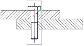
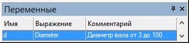
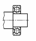
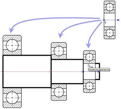
An important role is played by the external variables of the fragment for linking the parameters of the fragment and the assembly drawing. For example, the drawing contains an image of a shaft whose diameter has been assigned the variable " diameter".
Suppose you need to place a bearing on the shaft. A variable has been created in the bearing drawing " d ", which is responsible for the value of the inner diameter of the bearing. Variable " d " is marked as external. All other parameters of the bearing are related in such a way that they depend on the value " d".
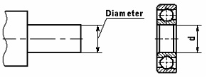
Now, when the bearing is applied to the shaft drawing, it will be possible to relate the two variables to each other. After these actions, changing the diameter of the shaft, that is, the variable " Diameter "assembly drawing, will automatically change the variable" d " of the fragment, which will lead to the necessary change in its image.

When designing a fragment in the variable editor, you can set the name of the assembly variable for an external variable. If later, when inserting a fragment in the assembly drawing, the system finds a variable with this name, it will automatically be associated with the corresponding external variable of the fragment.
To automatically set links between the values of fragment variables and the variables of other fragments in the assembly, you can use the mechanism connectors.
When working with a large number of external fragment variables, it is convenient to use configuration .
Configurations are a named set of values of external variables of the document and the 3D geometry corresponding to these values stored in the document. In a 2D document, only the values of external variables are stored in the configuration. For more information about working with configurations, see the “Configurations” section.
If configurations are created in the 2D fragment document, then when inserting or editing a fragment, you can select one of the fragment configurations. All external fragment variables will automatically be assigned the values stored in the selected configuration.
The name of the configuration to use can be set to a variable. If the value of this variable changes, the system will select the appropriate model configuration and change the values of the fragment variables automatically.
Controlling the visibility of fragment drawing elements
The part drawing may contain an image that does not need to be included in the Assembly drawing. Or it may be that, depending on the situation, we need to use one or another part of the drawing of the same part (for example, in one case we need a top view, in another case a front view). The visibility of the fragment drawing elements included in the assembly can be controlled using layers or visibility levels. When using layers, there are two options.
The first is to use the layer's own attributes ("Invisible when inserted into an assembly", " Visible only when inserted into an assembly"). This method does not allow you to organize several variants of the image of a fragment based on one drawing, however, it can be used to hide / show elements of the drawing of a fragment part, which are certainly necessary in the drawing of the part, but should be absent in the assembly (or vice versa). For example, it can be the dimensions of the part, the format, etc.
The second method is more flexible and can be used when positioning a fragment according to the anchor vector. Anchor vector parameters can specify how it is associated with the selected layers (see "Anchoring Vectors"). By creating several anchor vectors in the drawing with various options links with layers, you can get several options (for example, views) of a part based on one drawing.
The visibility of the elements of a fragment drawing using visibility levels is controlled by general rules, just like for all other drawing elements. This method may require the use of external fragment variables: to control the visibility levels of the fragment drawing, external variables can be created in the fragment, which can be transferred to the assembly document to control the image of the part. The visibility levels of the elements of the fragment drawing, adjusted by the values of external variables, both when editing in the context of the assembly and when detailing, will be reflected in accordance with the values of the variables in the assembly.
Removing Hidden Lines in an Assembly Drawing
One of the important advantages of T-FLEX fragments is the ability to remove hidden lines when creating an assembly from fragments. This allows, on the one hand, to create a complete drawing of the required part, and on the other hand, to “hide” those lines of this drawing that are covered by the image of other parts of the assembly drawing.
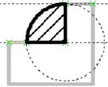
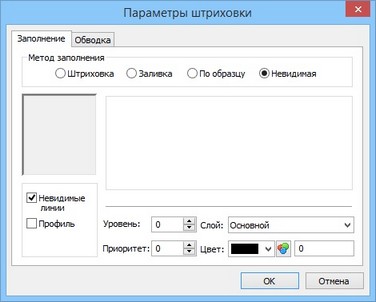
The area of the drawing on which it is necessary to provide for the removal of hidden lines is specified using hatching. To remove invisible lines, you can use an existing hatch or create an additional invisible one (using the fill method - "Invisible"). In the hatching options, check the box " invisible lines ". In this case, invisible hatching will hide objects with a lower priority underneath. The visibility of the overlapped element is adjusted by setting the corresponding priority in its properties. If the assembly lines should cover the lines of a fragment, then you will have to create a hatch in the assembly drawing itself, and then set a priority for it higher than the priority of the corresponding fragment.
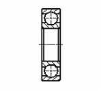
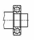
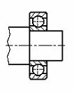
Consider the removal of invisible lines on the example of a drawing of a shaft and a fragment of a bearing. In the shaft drawing, you need to create a hatch to remove hidden lines. After applying the fragment to the assembly, the image of the fragment-bearing will overlap the image of the shaft. In order for the image of the shaft to cover the lines of the bearing, it is necessary to set the priority of the fragment-bearing less than the priority of the outline-hatch for the shaft. This can be done immediately when drawing a fragment, and then when editing it.

After changing the priority of a fragment, you need to update the image by calling the command "RD: Refresh document windows" (by pressing
Binding to Fragment Elements
Although the lines and other elements of a fragment are not part of the drawing in which it is included, various assembly drawing elements can be based on them. Simple fragment graphic lines (arcs and segments) can be used at any time if object snap is enabled. So, you can outline the lines of the image of the fragment with new construction lines or build a size or other design element on them.
In addition to fragment image lines, fragment nodes can be used. To enable the use of fragment nodes, you need to activate certain settings. In a team " :Set System Settings"on the Bindings tab" " must be checked "Allow Snaps to\Fragment Nodes". This setting will allow you to create assembly drawing elements based on the named nodes of the fragment or the end points of the graphic lines. In this case, new nodes built on the nodes of the fragment will be created in transparent mode.
If the image of a fragment is highly saturated with different elements, working in transparent mode can be somewhat difficult. In this case, you can disable the previous setting and switch to forced modes for creating the necessary nodes from the fragment:
1. In the "N: Build Node" command, you can create only those fragment nodes that are really needed for further work with the assembly.
2. Named fragment nodes can be created automatically when inserting a fragment, if in the system settings (command " :Set System Settings", tab " Fragments ") checkbox is checked"Creating Named Nodes Automatically".
Create an Assembly BOM
Creating a specification is one of the important steps in working with an assembly model. Work with specifications is described in detail in the section "Product structure, reports. Specification".
To automatically fill in the fields of the specification, it is necessary that the parts (fragments) of the assembly drawing contain a set of relevant data. The data for the specification is set in the fragment detail document in the "Product structure" window at any stage of work. When you include a fragment in an assembly, you can provide a way to use nested elements (other fragments) and their data in the assembly product structure. This allows you to include information about nested fragments in the assembly product structure, or to add data from the product structure located in the fragment document. Setting the appropriate mode makes it easier to generate BOMs for multilevel assemblies.
To obtain an assembly document specification, you must perform the following steps:
1. In the fragment document, fill in the data for the specification in the "Product structure" window.
2. In the assembly document in the fragment parameters or in the command " :Inclusion in the product structure" (" Service|Reports/Specifications|Inclusion of fragments in the product structure") define the method for including the fragment in the product structure.
3. With the command " :Create report/spec" you can generate an assembly specification.
Assembly drawing changes are automatically reflected in the BOM. If necessary, an unlimited number of reports or specifications can be associated with an assembly drawing.
Fragment-based detail drawings
When creating an assembly, drawings of fragments can be changed in accordance with the assembly parameters by changing external variables of fragments or the entire image during associative linking. File drawings-fragments do not change. However, if necessary, you can automatically obtain separate documents, which will contain drawings of fragment parts with parameters corresponding to the assembly parameters. We will call such drawings detail drawings. Detailed drawings can be obtained for the entire set of parts that make up the assembly drawing. When you create a detail drawing, no link is retained to the original assembly drawing.
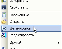
To get a detailed drawing, you need to use the optioncommands "FR: Create Fragment" or "EFR: Edit Fragment" or the "Detail" command in the context menu for the fragment. After calling the command, a new document window will open, into which a copy of the fragment drawing will be loaded with the values of external variables and associative links substituted from the assembly. The new drawing will be named "Part" with a serial number, for example, "Part 1". This drawing will be defined by the system as new, that is, when you try to close it, the system will prompt you to set the name of the drawing to save.
Typically, detail drawings are used to print drawings of parts that may differ from the original fragment drawing, for example, by changing assembly variables. In this case, it is not even necessary to save an electronic copy of the detailed drawing. This is convenient if the parametric fragment used in the assembly contains a fully completed drawing, and when creating a detailing, the user instantly receives a set of new documentation for the required part.
Revealing Fragments
The fragment applied in the assembly can be "revealed". In this case, the fragment is deleted, and instead copies of all visible elements of the fragment are created in the assembly drawing.
The system can expand the selected fragments in two ways, turning them into a set of drawing elements, with or without the original constructions. In the first case, all parametric links between the elements of the former fragment are saved and all necessary construction lines are transferred from the fragment drawing to save the parametric links of the former fragment drawing. In the second case, the fragment turns into a set of graphic lines based on free nodes.

A fragment containing nested fragments is expanded into the image elements and fragments it contains. After applying the expand option, the received elements can be handled as usual, according to their type.
If any elements (dimensions, construction lines, etc.) were created on the basis of the fragment elements in the assembly drawing, then after opening the fragment they will be reattached to the elements created when opening the fragment (nodes, construction lines and images).
Using Connectors
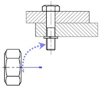
When creating assembly documents, it often becomes necessary to link the parameters (variables) of the inserted elements with the parameters of the elements to which the binding is made. For example, fitting a bearing onto a shaft, tying a cover to a bearing, keys to a keyway, nuts to a bolt, inserting a screw or stud into a hole, etc. When inserting such elements, the user is required not only to specify the main dimensional parameters (diameter, length, etc.), but also to accurately position the inserted element relative to the existing one (choose the anchor point and direction). One way to deal with this issue is to use the "measurement" mechanism, which, however, often requires a large number ancillary activities. Significantly simplify the procedure for inserting elements into the assembly model and minimize the number of user actions allowsconnector mechanism.
The basis of this mechanism is a "connector" - a construction element designed to bind other elements to it. In fact, the connector is analogous to the anchor vector or target anchor LCS for 3D fragments. Its main difference from the binding vector is that the connector is used to bind other elements of the model to it. So, for example, using the anchor vector, we can apply the image of a nut to the assembly drawing. Suppose the image of the bearing should be attached to the shaft, then the connector should be associated with the image (fragment) of the shaft.
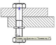
In addition to the geometric position (the position of the origin of the coordinate system and the direction of the axes), the connector can store other information necessary to “connect” other elements to it.
The information in the connector is stored as named values, which can be either constants or variables. The names of these values are used to set the values of the corresponding external variables of the fragments connected to them. For example, a connector located on the axis of the hole can have the depth and diameter of the hole as such parameters. When inserting a stud into this hole, its diameter can be set automatically by the D value stored in the connector. This requires that the external variable that specifies the diameter of the stud be also named "D".
There are a number of nuances when connecting a fragment to a connector:
● The connector is a construction element and may not be visible on the main drawing. However, it must be selected when connecting a fragment to it.
● The connector may be located at a point that is not shown in the drawing.
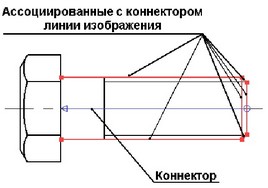
● Sometimes it is convenient to connect an element to the connector that is located away from it. For example, when binding a cover to a bearing, it is convenient to select the lines of the bearing itself, which lie on its periphery. In this case, the connector lying on the axis of the bearing must be selected.
To address these issues and improve visibility, the concept of "associated elements" is introduced, the list of which is stored in the connector. Associated elements are necessary for the full use of the object snap mechanism when connecting to a connector. When you move the cursor over one of the graphic lines associated with the connector, the connector is automatically activated (highlighted on the screen) and the fragment's external variables get the corresponding values taken from the connector. The 2D fragment is automatically recalculated with the new values of the variables and placed on the connection point with the appropriate orientation.
All libraries of standard T-FLEX CAD elements are already equipped with connectors and prepared for their use. Responsible external variables have predefined named values for connection with connectors.
Composite document. Nested Fragments
T-FLEX CAD has a mechanism that allows you to control how links to other documents (fragments, pictures, external databases, etc.) are stored. A T-FLEX CAD document can store links to external files (“external link”) or data from external files can be stored directly inside a T-FLEX CAD compound (assembly) document file (“internal link”). The same mechanism allows you to quickly transfer the assembly model to another location in the file system, pack the assembly model into one file with the possibility of subsequent unpacking.
To manage links in the system, a group of commands " File|Build... ". Working with the commands of this group is described in the chapter “Links. Compound Document Management”.
Keyboard |
Text menu |
Pictogram |
File|Assembly|Move assembly... |
Team " UL: Update Links” reloads the data of the external files of the first level included in the compound document.
Dimensions on assembly drawings can be divided into two groups:
1. The dimensions that must be made or controlled according to this assembly drawing are, as a rule, the execution dimensions.
2. Dimensions that are not subject to execution according to this assembly drawing and are indicated for greater convenience in using the drawing, these are, as a rule, reference dimensions.
The first group of sizes includes:
a) mounting dimensions indicating mutual arrangement
parts in products, these include mounting clearances. Often mutual
the location of the parts is determined by the combination of their mating
surfaces, such as mating surfaces. Therefore, mounting
dimensions on the assembly drawings may be missing;
b) the dimensions of the elements of the parts that are performed in the process
or after assembly, for example, by machining after
welding, riveting, soldering, pressing;
c) the dimensions of the mating elements of the parts that determine
the nature of the connection (fit), for example, the mating size with limit deviations cylinder and piston diameters:
d) dimensions characterizing operational parameters
products and positions of individual structural elements; to them, for example
measures include piston stroke, engine valve, lever.
The second group of sizes includes:
a) overall dimensions that determine the maximum external
the (internal) outline of the product, such as the height, length and width of the product or its largest diameter;
b) installation and connecting dimensions, which determine the dimensions of the elements by which this product is installed at the installation site or attached to another product; these include the dimensions of the center circles on the flanges along which the holes are located, and the diameters of the holes for the bolts, the distances between the mounting holes, the connecting dimensions of the threads, etc.;
On the drawings of assembly units, those dimensions are affixed that must be made and controlled according to this assembly drawing, that is, all executive dimensions, including dimensions for making permanent joints (riveting, welding, soldering, pressing). From the group of reference dimensions indicate the installation, connecting, overall, and from the characteristic - some dimensions that determine specifications assembly unit, for example, lever arms and their travel. Note that some of the installation, connecting and operational dimensions can be made according to the drawing during the assembly process. The drawing of the assembly unit must not contain those images that are given only to identify the shape and size of the elements of the parts (these images are typical for drawings general view and are necessary only for the development of working documentation).
Dimensioning on assembly drawings is due to the calculation, layout, technology requirements and operating conditions of products. By assigning them, the designer thus requires their exact execution during the assembly process or the exact relationship, coordination of all constituent parts.
According to the assembly drawing of the product, the worker must correctly understand the principle of operation, the interaction of parts, then, using the main image and number, make sure that the required part has arrived at the assembly, read the installation dimensions, understand how the parts are connected, find out the dimensions necessary for additional processing in the process assemblies, as well as specifications for testing, movement of parts, coatings, etc.
On the assembly drawings of the product for all sizes of mating elements of parts, both movable and fixed, as a rule, they give indications of the nature of the connection (fit - tolerance fields) and quality (accuracy class). The nominal dimensions are put down, related to both the hole and the shaft, and to the right of the nominal dimensions, an entry is given in the form of a simple fraction with the hole fit in the numerator and the shaft fit in the denominator. This information is necessary for the worker for the strict execution of the connection, as well as for the repair of the product.
The designation of the fit (for example, on assembly drawings in joints) includes a nominal size common to both connected elements of parts - holes and shafts, followed by designations of tolerance fields for each element starting from the hole. In this case, three forms of designation are possible: 0 14 H7/g6(preferred), 0 14 H7-g6 0 14 H7/g6. These designations correspond to the following landing designation according to OST 0 14 HELL. By the position number of fasteners (on the drawing of the assembly unit) and by the designation in the specification, you can find out their diameter.
For assembly units, which include one main (complex) part and several simple parts or standardized products (ball bearings, bushings, etc.), connected by pressing, flaring or in other ways, it can be advantageous to combine the assembly drawing with the drawing of the main part. In such a combined drawing, in addition to the considered information necessary for assembly, all dimensions and other data for the manufacture and control of the main part are given. Separate drawings are issued only for other simple parts. The designation and name of the main part are assigned according to general rules, and in the specification in the column "Format" they write BC (which means: "Without a drawing"). The complexity of the execution of technical documentation for the assembly unit by this method is reduced by 20-60%, depending on the complexity of the main part.
Assembly drawing are a certain type of design documentation that contains graphic and textual information about all the details that make up a product. According to the assembly drawings, as you might guess from the name itself, various components and assemblies are assembled.
One of the main requirements for assembly drawings is that there should be a minimum of them, but together they should provide the entire assembly and quality control process. finished products. Where necessary, the assembly drawings indicate how the interaction takes place. various parts structures and assembly units.
One of the main purposes of the assembly drawing is to create a complete picture of the composition of the assembly unit, as well as what its functional purpose is.
On the basis of assembly drawings, ready-made technical devices, and as the most simple knots, and mechanisms that are very complex in design.
assembly drawings give an idea of how various parts of machines and mechanisms are located relative to each other, as well as how they interact with each other.
All products on the assembly drawings are shown only in assembled form.
The assembly drawings depict various sections, cuts and standard views of products. Thanks to which it becomes possible to identify which device the assembly units have, as well as how the parts that make up them are interconnected.
Hatching parts on the assembly drawingThe main rule for hatching on sections and sections of assembly drawings is that it is done with lines of a certain thickness directed in the same direction. In this case, the distance between them should be the same.
In cases where it is required to depict parts in contact with each other on sections or sections of assembly drawings, hatching at an angle of 45 ° is carried out by lines located opposite to each other. In this case, it is also possible to change the distance between the dashed lines. In addition, you can hatch without changing the direction of the lines, but with a shift between them or with a change in distances.
In cases where the width of the sections on the assembly drawings is less than two millimeters, they are made not shaded, but blackened.
Details such as handles, connecting rods, spindles, non-hollow shafts, keys, rivets, washers, studs, bolts and screws are shown uncut in longitudinal sections of assembly drawings. In other sections, they are depicted as dissected.
Dimensions applied on assembly drawingsMandatory attributes of all assembly drawings are dimensions that are set in order to characterize both the assembly itself or the device as a whole, and those parameters that should be met both during its assembly and when controlling individual parameters. These dimensions are divided into overall, installation, connecting, mounting and reference.
1) Using overall dimensions parameters such as length, height, and width that are external are displayed.
2) In order to correctly install this or that assembly unit, installation dimensions are used. They define quantities such as center-to-center distances for screws, bolts, studs, etc.
3) Connecting dimensions are those that ensure the fastening of the products shown on the assembly drawings to other units and assemblies. It often happens that the connecting dimensions are also installation dimensions.
4) In order to correctly mount the parts in relation to each other, mounting dimensions are used (eg distances between center and center lines).
5) A feature of reference dimensions is that they are affixed only when it is dictated by necessity. It happens that on the assembly drawings, all available dimensions are reference.
In addition to dimensions, assembly drawings can also indicate such indicators as those dimensions that determine the extreme positions of individual moving parts of the structure, as well as those that are necessary for additional processing of its various constituent parts.
In addition to the listed dimensions, assembly drawings may contain additional indicators, such as: coordinates of the center of gravity of the product; dimensions, according to which additional processing of individual components will be carried out during the current assembly; dimensions that determine the extreme position of the moving parts of the products.
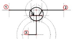
Position numbers on the assembly drawingThe images of the parts that are on the assembly drawings are assigned separate serial numbers, called positions.
With the help of positions, a link is made between the textual information contained in the specification and the images of individual parts. Positions greatly facilitate the search for images of the necessary parts.
Position numbers are depicted on assembly drawings in fonts that are one or two numbers larger than the one used to display dimensional numbers.
Thin lines are used to depict leader lines in assembly drawings, and there are certain rules for drawing them and grouping them into columns and lines. An important requirement for them is that they should not intersect with each other. In addition, it is highly desirable that they intersect as few images as possible in the drawings.
ASSEMBLY DRAWINGS
assembly drawing requirements
Rules for the execution and design of assembly drawings are established GOST 2.109-73.
Assembly drawing(SB) - contains an image of the assembly unit and other data necessary for its assembly and control.
Text documents include:
Specification- a document defining the composition of the assembly unit.
The number of assembly drawings should be minimal, but sufficient for the rational organization of production (assembly and control) of products. If necessary, assembly drawings provide data on the operation of the product and on the interaction of its parts.
The assembly drawing must contain:
Images of the assembly unit, while the image of other components of the product in thin lines is allowed;
Dimensions - overall, controlled according to this assembly drawing, connecting, mating, installation, reference. It is allowed to use as reference dimensions the dimensions of the parts that determine the nature of the connection;
Instructions on the use of permanent connections;
Position numbers of connected parts;
Product specifications (if necessary).
The assembly drawing is made with simplifications. For example, small elements (chamfers, fillets, etc.) are not shown on the assembly drawing.
The assembly drawing must contain:
a) an image of the assembly unit, giving an idea of the location and interconnection of the components connected according to this drawing, and providing the possibility of assembly and control of the assembly unit.
It is allowed to place additional schematic images of the connection and location of the component parts of the product on the assembly drawings;
b) dimensions, limit deviations and other parameters and requirements that must be met or controlled according to this assembly drawing.
It is allowed to indicate as a reference the dimensions of the parts that determine the nature of the pairing;
c) instructions on the nature of the pairing and methods for its implementation, if the accuracy of the pairing is ensured not by the specified maximum deviations of dimensions, but by selection, fitting, etc., as well as instructions on the implementation of permanent joints (welded, soldered, etc.);
d) the position numbers of the components included in the product; e) overall dimensions of the product;
f) Mounting, connecting and other necessary reference dimensions;
g) technical characteristics of the product (if necessary);
h) coordinates of the center of mass (if necessary) if they are not given in another design document, for example, on a dimensional drawing.
When specifying the installation and connecting dimensions, the following must be applied:
Location coordinates, dimensions with maximum deviations of elements used for connection with mating products;
Other parameters, for example, for gears serving as external link elements, module, number and direction of teeth.
On the assembly drawing, it is allowed to depict the moving parts of the product in the extreme or intermediate position with the appropriate dimensions. If, when depicting moving parts, it is difficult to read the drawing, then these parts can be depicted on additional views with appropriate inscriptions, for example: “The extreme position of the carriage pos. 5".
On the assembly drawing of the product, it is allowed to place an image of border (neighboring) products ("environment") and dimensions that determine their relative position (Fig. 30).
The component parts of the product, located behind the situation, are depicted as visible. If necessary, it is allowed to depict them as invisible.
If it is necessary to indicate on the assembly drawing the names or designations of the products that make up the "furnishings" or their elements, then these indications are placed directly on the image of the "furnishings" or on the shelf of the leader line drawn from the corresponding image, for example: "Automatic pressure (designation )"; "Oil cooler connection (designation)", etc.
On the assembly drawing of an auxiliary production product (for example, a stamp, a conductor, etc.), it is allowed to place an operational sketch in the upper right corner.
Assembly drawings should be performed, as a rule, with simplifications that meet the requirements of the standards of the Unified System for Design Documentation and this standard.
Products made of transparent material are depicted as opaque.
It is allowed on assembly drawings to depict the components of products and their elements located behind transparent objects as visible, for example: scales, instrument arrows, the internal arrangement of lamps, etc.
Products located behind a helical spring, shown only by sections of coils, are depicted up to a zone conditionally covering these products and determined by center lines sections of turns (Fig. 31).
On assembly drawings, the following methods of simplified representation of the components of products are used:
on the cuts, the components are depicted as undissected, for which independent assembly drawings are drawn up.
On assembly drawings that include images of several identical components (wheels, track rollers, etc.), it is allowed to perform a complete image of one component, and images of other parts - simplified in the form of external outlines.
A welded, soldered, glued and similar product made of a homogeneous material assembled with other products in cuts and sections is hatched in one direction, depicting the boundaries between the parts of the product with solid main lines (Fig. 35).
It is allowed not to show the boundaries between the details, i.e. to depict the structure as a monolithic body.
The moving parts of the product are depicted in the extreme or intermediate position by the line -.. -..-
It is allowed not to show:
(spring - center line). "pos. 3 - cover not shown).
Those parts of the product for which independent drawings are drawn up are depicted as undissected.
Seal - arrow.
Adjacent parts - with different hatching or inclination (hatching is the same on all sheets of the same part)
Elements less than 2 mm thick are blackened.
In non-detachable connections - hatching is one or with a border.
It is allowed to depict details on the drawing field for which there are no separate drawings
On assembly drawings it is allowed not to show:
a) chamfers, roundings, grooves, recesses, protrusions, knurling, cuts, braids and other small elements;
b) gaps between the rod and the hole;
c) covers, shields, casings, partitions, etc., if it is necessary to show the component parts of the product closed by them. At the same time, a corresponding inscription is made above the image, for example: “Cover pos. 3 not shown";
d) visible components of products or their elements located behind the mesh, as well as partially closed in front of the components located in front;
e) inscriptions on plates, nameplates, scales and other similar details, depicting only their outline.
Position numbers
On the assembly drawing, all components of the assembly unit are numbered in accordance with the position numbers indicated in the specification of this assembly unit. Position numbers are applied on the shelves of leader lines drawn from the images of the component parts.
Position numbers indicate those images on which the corresponding components are projected. as visible as a rule, on the main views and sections replacing them.
Item number have parallel to the main drawing labels outside the image outline and group in a column or line if possible on one line.
The position number is applied on the drawing, as a rule, once. It is allowed to repeat the position numbers of identical components.
The font size of the item numbers should be one or two numbers more than the font size adopted for dimensional numbers in the same drawing.
Allowed to do common leader line with vertical arrangement of item numbers:
a) for a group of fasteners related to the same attachment point (Fig. 36). If there are two or more fasteners, and at the same time different components are fastened with the same fasteners, then their number can be put in brackets after the number of the corresponding position and indicated only for one unit of fasteners.
of the constituent part, regardless of the number of these constituent parts
in the product;
b) for a group of parts with a clearly expressed relationship, excluding a different understanding, if it is impossible to draw a leader line to each component (Fig. 37).
In these cases, the leader line is removed from the fixed component;
c) for individual components of the product, if it is difficult to graphically depict them, in this case it is allowed not to show these components on the drawing, but to determine their location using a leader line from the visible component and on the drawing field, in the technical requirements to place the appropriate indication, for example: ,Tows pos. 12 under the brackets, wrap with pressboard pos. 22".
Execution of certain types of assembly drawings.
It is allowed to place separate images of several parts on the field of the assembly drawing, for which it is allowed not to issue working drawings, provided that the clarity of the drawing is maintained.
An inscription is applied above the image of the part containing the position number and the scale of the image, if it differs from the scale specified
in the title block of the drawing.
It is allowed not to issue drawings for:
Parts made of sectional material by cutting along the circumference, at an angle, along the perimeter
Surfacing, pouring
One-piece, glued, soldered, simple
Purchased
Specification
The specification is drawn up on separate sheets for each assembly unit, complex and kit according to forms 1 and 1a.
The specification is the main design document, determines the composition of the assembly unit, complex and kit and is necessary for the manufacture, acquisition of design documents and planning the launch of these products into production.
The specification includes the components included in the specified product, as well as design documents related to this product and its non-specified components.
The specification generally consists of sections, which are arranged in the following sequence:
documentation;
complexes;
Assembly units;
Standard products;
Other products;
materials;
kits.
The presence of certain sections is determined by the composition of the specified product. The name of each section is indicated as a heading in the column "Name" and underlined. After the section, leave a reserve line or 2.
- In the "Documentation" section"make the documents (designation) that make up the main set of design documents of the specified product.
- In the sections "Complexes", "Assembly units" and "Details" introduce complexes, assembly units and parts that are directly included in the specified product. Recording of these products is recommended to be done in the order increasing classification characteristics (in the first place is a noun).
- In the "Standard products" section"record products used for:
state standards;
republican standards;
industry standards;
enterprise standards (for a product of auxiliary production).
in alphabetical order of product names.
- in the section „Other products"They make products that are not used according to the main design documents (according to technical specifications), with the exception of standard products. Products are recorded in homogeneous groups; within each group - in alphabetical order of product names.
- In the section "Materials"contribute all the materials directly included in the specified product.
Materials are recorded by type in the following sequence: ferrous metals;
magnetoelectric and ferromagnetic metals;
non-ferrous, noble and rare metals;
cables, wires and cords; plastics and press materials;
paper and textile materials;
timber;
rubber and leather materials;
mineral, ceramic and glass materials;
varnishes, paints, petroleum products and chemicals;
Other materials.
Within each type, materials are recorded in alphabetical order of names, and within each name - in ascending order of size or other technical parameters.
- In the "Sets" section"They enter a list of operational documents, a list of documents for repairs and kits used according to design documents that are directly included in the specified product, as well as packaging intended for the product, and write them down in the following sequence:
Statement of operational documents;
List of documents for repair;
Set of mounting parts;
Set of replacement parts;
Spare parts;
Set of tools and accessories;
A set of styling products;
Other kits (for the names assigned to them);
If the kit includes no more than three items, then the kit can be omitted, and the products included in the kit must be recorded directly in the specification of the corresponding product in the “Kits” section. product specification, write in the column "Name" as a heading and do not underline. (Revised edition, Rev. No. 3).
The specification columns are filled in as follows:
a) in the column "Format" indicate the formats of documents, the designation of which is recorded in the column "Designation". If the document is made on several sheets of different formats, then an “asterisk” is put down in the column, and all formats are listed in the “Note” column in increasing order.
For documents recorded in the section "Standard products", "Other products" and "Materials", the column is not filled in.
For parts for which drawings are not issued, the column indicates: BC.
For documents published by typographic, lithographic and similar methods in the formats provided for by the relevant state standards for typographic publications, a dash is put in the column;
b) in the column "Zone" indicate the designation of the zone in which the position number of the recorded component is located (when the drawing field is divided into zones according to GOST 2.104-68).
c) in the column "Pos." indicate the serial numbers of the components that are directly included in the specified product, in the sequence of recording them in the specification. For sections. Documentation "and" Kits "the column is not filled in;
d) in the column "Designation" indicate:
in the "Documentation" section - the designation of the recorded documents;
in the sections "Complexes", "Assembly units", "Details" and "Kits" - designations of the main design documents for the products recorded in these sections. For parts for which drawings are not issued, the designation assigned to them.
In the sections "Standard products", "Other products" and "Materials" the column is not filled in. If design documentation has been issued for the manufacture of a standard product, the designation of the issued main design document is indicated in the column "Designation";
e) in the column "Name" indicate:
In the "Documentation" section for documents included in the main set of documents of the specified product and compiled for the product, only the name of the documents, for example: "Assembly drawing", "Dimensional drawing", "Specifications".
in the section "Materials" - the designations of materials established in the standards or specifications for these materials.
e) in the column "Number." indicate:
for the component parts of the product recorded in the specification, their number per one specified product;
in the "Materials" section - the total amount of materials for one specified product, indicating the units of measurement. It is allowed to write down the units of measurement in the "Note" column in the immediate vicinity of the "Quantity" column.
In the "Documentation" section, the column is not filled;
g) in the column "Note" indicate additional information for planning and organizing production, as well as other information related to the products, materials and documents recorded in the specification, for example, for parts for which drawings are not issued - weight.
For documents issued on two or more sheets of different formats, indicate the designation of the formats, before the listing of which an asterisk is put down, for example: *) A4, A3.
After each section of the specification, it is necessary to leave a few free lines for additional entries (depending on the stage of development, the volume of entries, etc.). It is allowed to reserve the position numbers that are put down in the specification when filling out the reserve lines.
It is allowed to combine the specification with the assembly drawing, provided that they are placed on an A4 sheet (GOST 2.301-68). At the same time, it is placed above the main inscription and filled in in the same order and in the same form as the specification, made on separate sheets.
For products of auxiliary production and single-piece production of one-time production, it is allowed to combine the specification with the assembly drawing on sheets of any format established by GOST 2.301-68. The rules for the execution and circulation of such combined documents are established in industry standards. The combined document is assigned the designation of the main design document. The main inscription is performed in accordance with GOST 2.104-68 (form 1).
The columns "Mass" and "Material" are filled in as follows:
a) in the column "Mass" indicate:
for parts for which drawings are not issued - the mass of one part;
For materials, the mass of material per specified item;
b) in the column "Material" for parts for which drawings are not issued, they indicate the designations of materials established in the standards for these