Dimensions on the drawing according to the quality. Application of limit deviations of dimensions
Unified system for design documentation. Drawing of dimensions an limit deviations
Instead of GOST 3458-59, GOST 9171-59,
GOST 5292-60 in part III
This standard establishes the rules for applying dimensions and limit deviations on drawings and other technical documents for products of all industries and construction.
Primary requirements
1.1. The basis for determining the size of the depicted product and its elements are the dimensional numbers printed on the drawing.
The exception is the cases provided for in GOST 2.414; GOST 2.417; GOST 2.419, when the size of the product or its elements is determined from images made with a sufficient degree of accuracy.
The basis for determining the required accuracy of the product during manufacture is the maximum deviations of dimensions indicated on the drawing, as well as the maximum deviations of the shape and location of surfaces.
1.2. The total number of dimensions in the drawing should be minimal, but sufficient for the manufacture and control of the product.
1.3. Dimensions that are not subject to execution according to this drawing and are indicated for greater ease of use of the drawing are called reference.
1.4. Reference dimensions in the drawing are marked with an "*", and in technical requirements write down: "* Dimensions for reference". If all dimensions in the drawing are reference, they are not marked with a "*" sign, and in the technical requirements they write: "Dimensions for reference".
On construction drawings, reference dimensions are noted and specified only in cases provided for in the relevant documents approved in the prescribed manner.
1.5. Reference sizes include the following:
a) one of the sizes of a closed dimensional chain. Limit deviations of such dimensions are not indicated in the drawing (Fig. 1);
"Drawing 1. An example of the size of a closed dimensional chain"
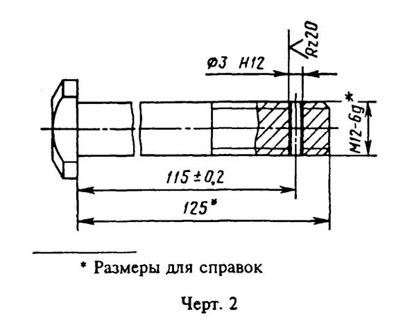
b) dimensions transferred from the drawings of blank products (Fig. 2);
c) dimensions that determine the position of the elements of the part to be processed on another part (Fig. 3);
"Drawing 2. Dimensions transferred from the drawings of blanks"

"Drawing 3. Dimensions that determine the position of the elements of the part to be processed on another part"
d) dimensions on the assembly drawing, which determine the limit positions of individual structural elements, for example, piston stroke, valve stem stroke of an internal combustion engine, etc .;
e) dimensions on the assembly drawing, transferred from the drawings of parts and used as installation and connecting ones;
e) dimensions on the assembly drawing, transferred from the drawings of parts or being the sum of the dimensions of several parts;
g) the dimensions of parts (elements) from sectional, shaped, sheet and other rolled products, if they are fully determined by the designation of the material given in column 3 of the main inscription.
Notes:
1. The reference dimensions indicated in subparagraphs b, c, d, f, g of this paragraph can be applied both with and without maximum deviations.
2. Installation and connecting dimensions are called, which determine the dimensions of the elements by which this product is installed at the installation site or attached to another product.
3. Dimensions are called dimensions that determine the limiting external (or internal) outlines of the product.
1.6. On the drawings of products, the dimensions, the control of which is technically difficult, are marked with an "*", and in the technical requirements the inscription "Dimensions of the provided tool" is placed.
Note. The indicated inscription means that the fulfillment of the size specified by the drawing with the maximum deviation must be guaranteed by the size of the tool or the corresponding technological process.
At the same time, the dimensions of the tool or the technological process are checked periodically in the process of manufacturing products.
Tool inspection frequency or technological process installed by the manufacturer together with the customer's representative.
1.7. It is not allowed to repeat the dimensions of the same element in different images, in technical requirements, in the main inscription and in the specification. The exception is the reference dimensions given in clause 1.5 b and g.
If in the technical requirements it is necessary to refer to the size printed on the image, then this size or the corresponding element is indicated by a letter, and in the technical requirements an entry similar to that shown in Fig. 4 is placed.
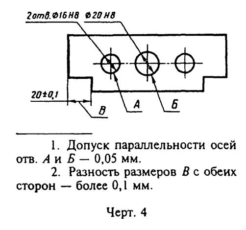
"Drawing 4. An example when in the technical requirements it is necessary to refer to the size applied to the image"
Dimensions may be repeated on construction drawings.
1.5 - 1.7.
1.8. Linear dimensions and their maximum deviations in the drawings and specifications are indicated in millimeters, without indicating the unit of measurement.
For dimensions and maximum deviations given in the technical requirements and explanatory inscriptions on the drawing field, the units of measurement must be indicated.
(Changed edition, Rev. N 3).
1.9. If the dimensions on the drawing must be indicated not in millimeters, but in other units of measurement (centimeters, meters, etc.), then the corresponding dimensional numbers are recorded with the designation of the unit of measurement (cm, m) or indicated in the technical requirements.
On construction drawings, units of measurement in these cases may not be indicated if they are specified in the relevant documents approved in the prescribed manner.
1.10. Angular dimensions and limit deviations angular dimensions indicate in degrees, minutes and seconds with the designation of the unit of measurement, for example: 4 °; 4°30"; 12° 45"30"; 0°30"40"; 0°18"; 0°5"25"; 0°0"30"; 30° +- 1°; 30° +- 10".
1.11. For dimensional numbers apply simple fractions not allowed, except for sizes in inches.
1.12. The dimensions that determine the location of the mating surfaces are affixed, as a rule, from constructive ones without taking into account the possibilities of performing and controlling these dimensions.
1.13. When the elements of the object (holes, grooves, teeth, etc.) are located on the same axis or on the same circle, the dimensions that determine them mutual arrangement applied in the following ways:
from common base(surfaces, axes) - according to drawing 5a and b;
setting the sizes of several groups of elements from several common bases - according to Fig. 5c;
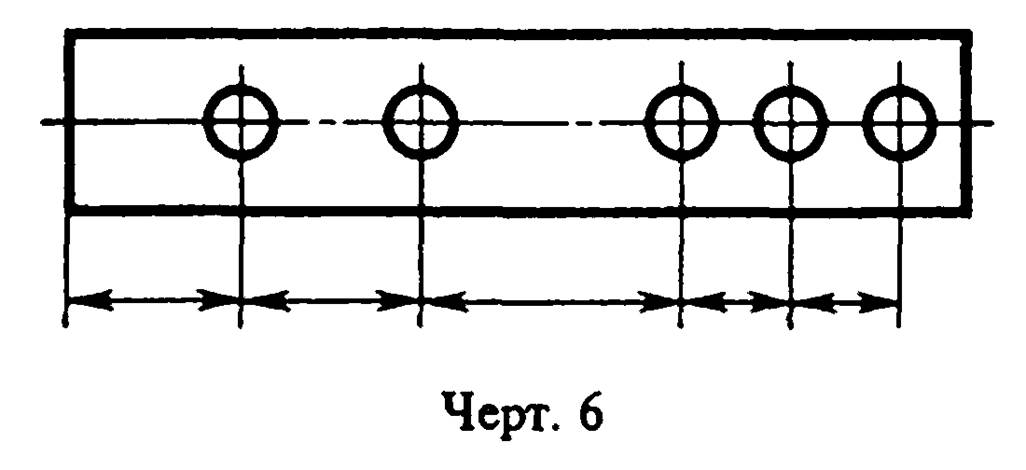
setting dimensions between adjacent elements (chain) - according to Fig.6.

"Drawing 5. Dimensioning when the elements of the object are located on the same axis or on the same circle"
"Drawing 6. Dimensioning when the elements of the object are located on the same axis or on the same circle"
1.14. Dimensions on the drawings are not allowed to be applied in the form of a closed chain, except when one of the dimensions is indicated as a reference (see drawing 1).
On construction drawings, dimensions are applied in the form of a closed chain, except as provided for in the relevant documents approved in the prescribed manner.
Dimensions that determine the position of symmetrically located surfaces of symmetrical products are applied as shown in Fig. 7 and 8.

"Drawing 7. Dimensions that determine the position of symmetrically located surfaces of symmetrical products"
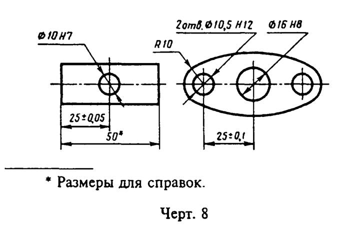
"Drawing 8. Dimensions that determine the position of symmetrically located surfaces of symmetrical products"
(Changed edition, Rev. N 2).
1.15. For all dimensions printed on the working drawings, limit deviations are indicated.
It is allowed not to indicate limit deviations:
a) for dimensions that define zones of different roughness of the same surface, heat treatment zones, coating, finishing, knurling, notches, as well as diameters of knurled and notched surfaces. In these cases, a sign is applied directly to such dimensions approximately;
b) for the dimensions of the parts of products of a single production, specified with an allowance for fit.
On such drawings, in the immediate vicinity of the indicated dimensions, the sign "*" is applied, and in the technical requirements they indicate:
"* Dimensions with an allowance for fitting according to children ...",
"* Dimensions with an allowance for fit according to hell....",
"* Dimensions with an allowance for fitting to the mating part."
On construction drawings, the maximum deviations of dimensions are indicated only in cases provided for in the relevant documents approved in the prescribed manner.
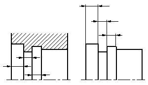
1.16. When making working drawings of parts manufactured by casting, stamping, forging or rolling, followed by machining of a part of the surface of the part, indicate no more than one size in each coordinate direction, connecting the machined surfaces with surfaces not subjected to machining (Fig. 9 and 10) .

"Drawing 9. Dimension designation when making working drawings of parts manufactured by casting, stamping, forging or rolling, followed by machining of part of the surface of the part"
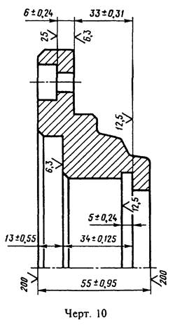
"Drawing 10. Dimension designation when making working drawings of parts manufactured by casting, stamping, forging or rolling, followed by machining of part of the surface of the part"
(Changed edition, Rev. N 2).
1.17. If the element is depicted with a deviation from the scale of the image, then the dimension number should be underlined (Fig. 10a).
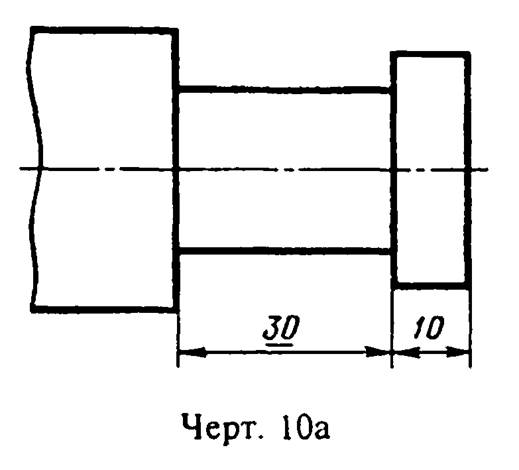
"Drawing 10a. Dimensional number designation if the element is depicted with a deviation from the image scale"
Dimensioning
2.1. Dimensions in the drawings are indicated by dimensional numbers and dimension lines.
2.2. When applying the size of a straight segment, the dimension line is drawn parallel to this segment, and the extension lines are perpendicular to the dimension lines (Fig. 11).
2.3. When applying the size of the corner, the dimension line is drawn in the form of an arc with a center at its vertex, and extension lines are drawn radially (Fig. 12).
2.4. When drawing the size of an arc of a circle, the dimension line is drawn concentric to the arc, and the extension lines are parallel to the bisector of the angle, and the "arc" sign is applied above the dimension number (Fig. 13).
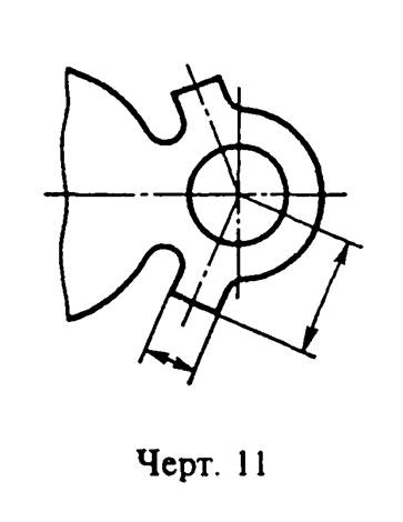
"Drawing 11. Applying the dimension of a straight line segment"

"Drawing 12. Applying the size of the corner"
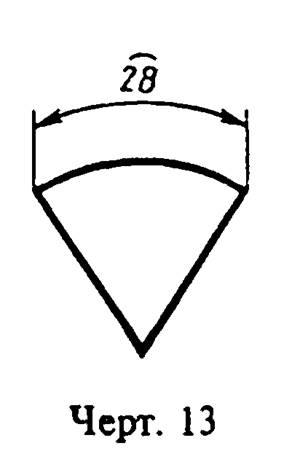
"Drawing 13. Applying the size of the arc of a circle"
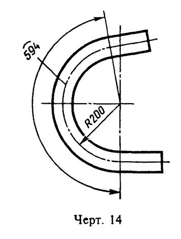
"Drawing 14 Arc Dimension Witness Line Location"
It is allowed to place the extension lines of the arc dimension radially, and if there are still concentric arcs, it is necessary to indicate to which arc the dimension belongs (Fig. 14).
2.4a. When applying the dimensions of parts similar to those shown in Fig. 14a, dimension lines should be drawn in the radius direction, and extension lines - along arcs of circles (Fig. 14a).
(Introduced additionally, Rev. N 2).
2.5. The dimension line at both ends is limited by arrows resting on the corresponding lines, except for the cases given in paragraphs 2.16, 2.17, 2.20 and 2.21, and when drawing a radius line bounded by an arrow from the side of the arc or fillet being determined.
On construction drawings, instead of arrows, it is allowed to use serifs at the intersection of dimension and extension lines, while the dimension lines should protrude beyond the extreme extension lines by 1 ... 3 mm.
"Drawing 14a. An example of applying the dimensions of parts"
2.6. In the cases shown in Fig. 15, the dimension and extension lines are drawn so that they, together with the measured segment, form a parallelogram.
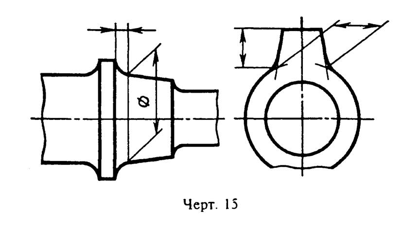
"Drawing 15. An example of drawing a dimension and extension lines, in which they, together with the measured segment, form a parallelogram"
2.7. It is allowed to draw dimension lines directly to the lines of the visible contour, axial, center and other lines (Fig. 16 and 17).

"Drawing 16. An example of drawing dimension lines directly to the lines of the visible contour, axial, center and other lines"
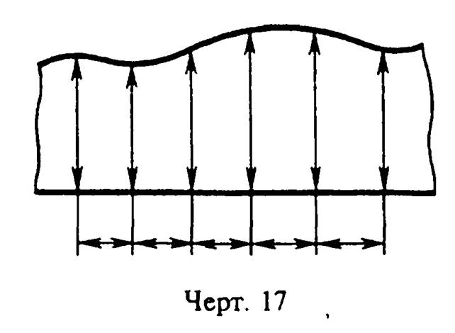
"Drawing 17. An example of drawing dimension lines directly to the lines of the visible contour, axial, center and other lines"
2.8. Dimension lines are preferably drawn outside the outline of the image.
2.9. Extension lines should extend beyond the ends of the arrows of the dimension line by 1 ... 5 mm.
2.10. The minimum distance between parallel dimension lines should be 7 mm, and between the dimension line and the contour line - 10 mm and are selected depending on the size of the image and the saturation of the drawing.
(Changed edition, Rev. N 2).
2.11. It is necessary to avoid the intersection of dimension and extension lines (see drawing 16).
2.12. Contour lines are not allowed; axial, center and extension lines as dimension lines.
2.13. Extension lines are drawn from the lines of the visible contour, except for the cases specified in paragraphs. 2.14 and 2.15, and cases when, when drawing dimensions on an invisible contour, there is no need to draw an additional image.
2.14. The dimensions of the contour of the curved profile are applied as shown in Fig. 16 and 17.
2.15. If it is necessary to show the coordinates of the vertex of the rounded corner or the center of the rounding arc, then the extension lines are drawn from the point of intersection of the sides of the rounded corner or the center of the rounding arc (Fig. 18).

"Drawing 18. An example of drawing extension lines, if you need to show the coordinates of the vertex of the rounded corner or the center of the rounding arc"
2.16. If a view or section of a symmetrical object or individual symmetrically located elements is depicted only up to the axis of symmetry or with a break, then the dimension lines related to these elements are drawn with a break, and the break of the dimension line is made further than the axis or break line of the object (Fig. 19).
On construction drawings, in such cases, all dimensions may be indicated only up to the axis of symmetry, and the dimension lines at the intersection with the axis of symmetry should be limited by a cross of serifs.
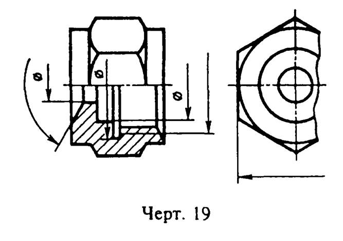
"Drawing 19. An example of the designation of dimension lines, if the view or section of a symmetrical object or individual symmetrically located elements is depicted only up to the axis of symmetry or with a break"
2.17. Dimension lines can be drawn with a break in the following cases:
a) when specifying the size of the diameter of a circle, regardless of whether the circle is shown in full or in part; at the same time, a break in the dimension line is made further than the center of the circle (Fig. 20);
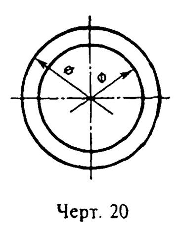
"Drawing 20. An example of drawing dimension lines with a break when specifying the size of the circle diameter"
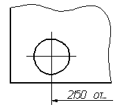
b) when applying dimensions from a base not shown in this drawing (Fig. 21).
2.18. When depicting a product with a break, the dimension line is not interrupted (Fig. 22).

"Drawing 21. An example of drawing dimension lines with a break when applying dimensions from a base not shown in this drawing"

"Drawing 22. An example of drawing a dimension line without a break when depicting a product with a break"
2.19. The values of the elements of the arrows of the dimension lines are selected depending on the thickness of the lines of the visible contour and are drawn approximately the same throughout the drawing. The shape of the arrow and the approximate ratio of its elements are shown in Fig.23.
(Changed edition, Rev. N 2).
2.20. If the length of the dimension line is insufficient to place arrows on it, then the dimension line is continued beyond the extension lines (or, respectively, beyond the contour, axial, center, etc.) and the arrows are applied as shown in Fig. 24.
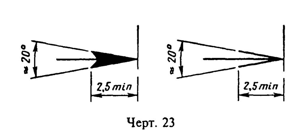
"Drawing 23. The shape of the arrow and the approximate ratio of its elements"
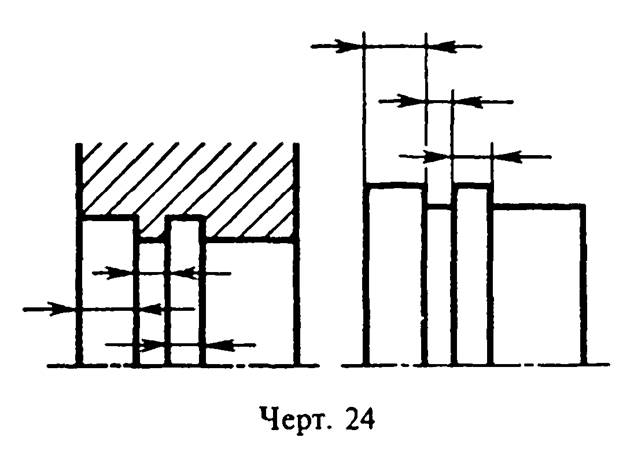
"Drawing 24. Drawing arrows if the dimension line is not long enough to place arrows on it"
2.21. If there is not enough space for arrows on dimension lines located in a chain, it is allowed to replace the arrows with serifs applied at an angle of 45 ° to the dimension lines (Fig. 25); or clearly marked dots (Fig. 26).
2.22. If there is not enough space for an arrow due to a closely located contour or extension line, the latter can be interrupted (Fig. 24 and 27).

"Drawing 25. If there is not enough space on the dimension lines located in a chain, the arrows can be replaced with serifs"
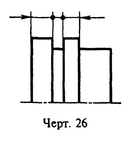
"Drawing 26. If there is not enough space on the dimension lines located in a chain, the arrows can be replaced with clearly marked dots"
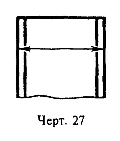
"Drawing 27. An example of interrupting a contour or extension line when there is not enough space for an arrow"
2.23. Dimensional numbers are applied above the dimension line as close as possible to its middle (Fig. 28).

"Drawing 28. Drawing dimensional numbers"
2.24. When applying the size of the diameter inside the circle, the dimension numbers are shifted relative to the middle of the dimension lines.
2.25. When applying several parallel or concentric dimension lines at a small distance from each other, it is recommended that the dimension numbers above them be staggered (Fig. 29).
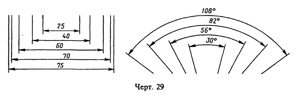
"Drawing 29. Location of dimension numbers when applying several parallel or concentric dimension lines at a small distance from each other"
2.26. Dimensional numbers linear dimensions at different slopes of the dimension lines, they are arranged as shown in Fig. 30.
If it is necessary to apply a dimension in the shaded area, the corresponding dimension number is applied on the shelf of the leader line (Fig. 31).
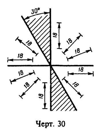
"Drawing 30. Arrangement of dimension numbers of linear dimensions with different slopes of dimension lines"
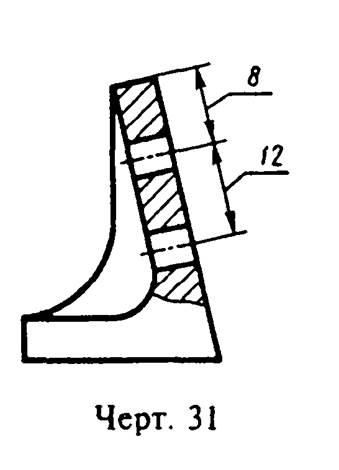
"Drawing 31. The location of the dimension number, if it is necessary to apply the dimension in the shaded area"
2.27. Angular dimensions are applied as shown in drawing 32. In the zone located above the horizontal center line, the dimension numbers are placed above the dimension lines from the side of their convexity; in the area located below the horizontal center line - from the side of the concavity of the dimension lines. It is not recommended to apply dimensional numbers in the shaded area. In this case, the dimension numbers indicate the horizontally applied shelves.
For corners of small sizes with a lack of space, dimension numbers are placed on the shelves of leader lines in any zone (Fig. 33).
2.28. On construction drawings, it is allowed to apply linear and angular dimensional numbers and inscriptions without shelves of leader lines.
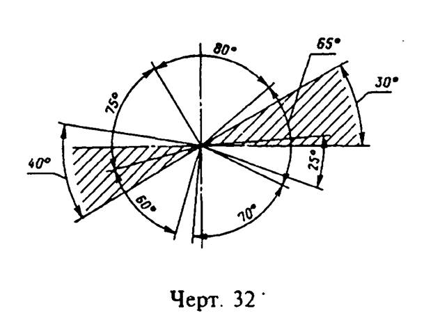
"Drawing 32. Applying angular dimensions"
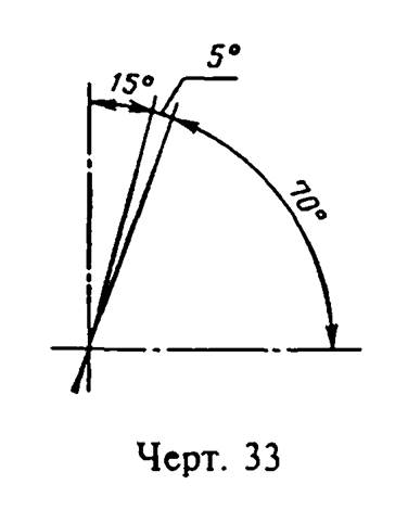
"Drawing 33. Location of dimension numbers for small corners with insufficient space"
2.29. If there is not enough space above the dimension line to write the dimension number, then the dimensions are applied as shown in Fig. 34; if there is not enough space for drawing arrows, then they are applied, as shown in Fig. 35.
The method of applying the dimension number at different positions of the dimension lines (arrows) in the drawing is determined by the greatest ease of reading.
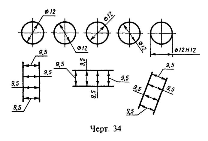
"Drawing 34. Applying dimensions if there is not enough space above the dimension line to write the dimension number"
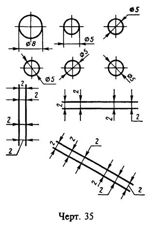
"Drawing 35. Drawing arrows if there is not enough space to draw them"
2.30. Dimensional numbers and limit deviations are not allowed to be divided or crossed by any lines of the drawing. It is not allowed to break the contour line for drawing a dimension number and apply dimension numbers at the intersection of dimension, axial or center lines. In the place where the dimension number is applied, the axial, center lines and hatching lines are interrupted (Fig. 36 and 37).
2.29, 2.30. (Changed edition, Rev. N 2).
2.31. Dimensions related to the same structural element(groove, protrusion, hole, etc.), it is recommended to group them in one place, placing them on the image on which geometric shape of this element is shown most fully (Fig. 38).
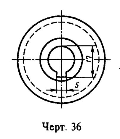
"Drawing 36. Location of dimensional numbers and limit deviations"

"Drawing 37. Location of dimensional numbers and limit deviations"

"Drawing 38. Arrangement of dimensions related to the same structural element"
2.32. When drawing a radius dimension, a capital letter R is placed in front of the dimension number.
2.33. If, when applying the size of the radius of an arc of a circle, it is necessary to specify the size that determines the position of its center, then the latter is depicted as an intersection of center or extension lines.
At big size radius, the center can be brought closer to the arc, in this case the dimension line of the radius is shown with a break at an angle of 90 ° (Fig. 39).
2.34. If it is not required to specify the dimensions that determine the position of the center of the circular arc, then the dimension line of the radius may not be brought to the center and shifted relative to the center (Fig. 40).
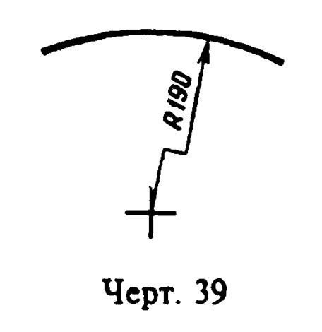
"Drawing 39. Drawing a dimension line with a large radius"
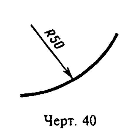
"Drawing 40. Drawing a dimension line, if you do not need to specify dimensions that determine the position of the center of the circular arc"
2.35. When drawing several radii from one center, the dimension lines of any two radii are not located on the same straight line (Fig. 41).
If the centers of several radii coincide, their dimension lines may not be brought to the center, except for the extreme ones (Fig. 41a).
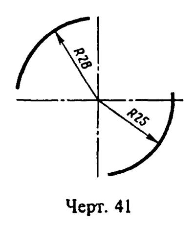
"Drawing 41. Location of dimension lines when drawing multiple radii from the same center"
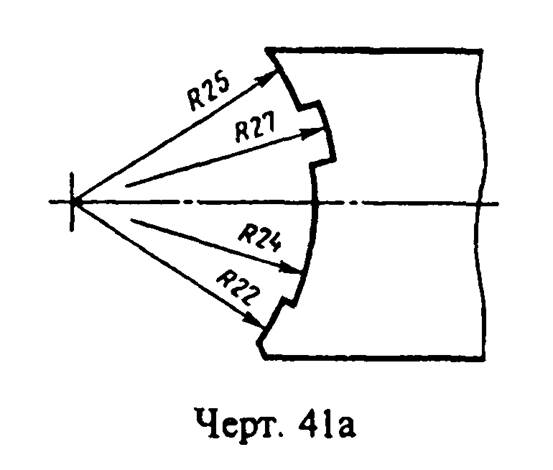
"Drawing 41a. Location of dimension lines when the centers of several radii coincide"
2.36. The dimensions of the radii of the outer fillets are applied, as shown in Fig. 42, of the internal fillets - in Fig. 43.

"Drawing 42. Dimensioning the radii of outer fillets"

"Drawing 43. Dimensioning the radii of internal fillets"
Rounding radii, the size of which is 1 mm or less on the scale of the drawing, are not shown in the drawing and their dimensions are applied, as shown in Fig. 43a.
The method of applying dimensional numbers at various positions of the dimension lines (arrows) in the drawing is determined by the greatest ease of reading. The dimensions of the same radii are allowed to be indicated on a common shelf, as shown in Fig. 43b.

"Drawing 43a. Drawing the dimensions of the rounding radii, the size of which is 1 mm or less on the scale of the drawing"
"Drawing 43b. Dimensioning the same radii"
If the radii of fillets, bends, etc. are the same throughout the drawing or some radius is predominant, then instead of drawing the dimensions of these radii directly on the image, it is recommended to make an entry in the technical requirements like: "Rounding radii 4 mm"; "Internal bend radii 10 mm"; "Unspecified radii 8 mm", etc.
2.35, 2.36. (Changed edition, Rev. N 2).
2.37. When specifying the size of the diameter (in all cases), the sign "Dia." is applied before the size number.
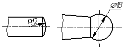
2.38. Diam. (R) without the inscription "Sphere" (Fig. 44). If it is difficult to distinguish a sphere from other surfaces in the drawing, then before the dimension number of the diameter (radius) it is allowed to put the word "Sphere" or the sign O, for example, "Sphere Diam.18, O R12".
"Drawing 44. Applying the dimension number of the diameter of the sphere"
The diameter of the sign of the sphere is equal to the size of the dimensional numbers in the drawing.
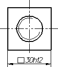
2.39. The dimensions of the square are applied as shown in Fig. 45, 46 and 46a.
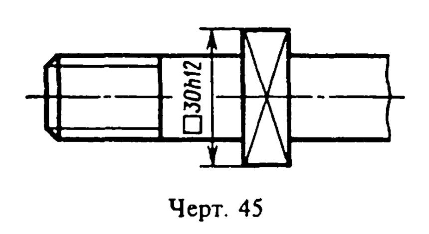
"Drawing 45. Applying the dimensions of a square"
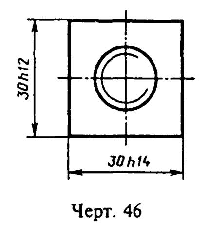
"Drawing 46. Applying the dimensions of a square"
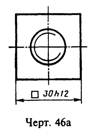
"Drawing 46a. Drawing the dimensions of the square"
The height of the sign must be equal to the height of the dimensional numbers in the drawing.
2.38, 2.39. (Changed edition, Rev. N 2).
2.40. Before the dimension number characterizing the taper, put the sign "<|", острый угол которого должен быть направлен в сторону вершины конуса (черт.47).

"Drawing 47. Drawing a dimensional number characterizing the taper"
The sign of the cone and the taper in the form of a ratio should be applied over center line or on the leader line shelf.
2.41. The slope of the surface should be indicated directly at the image of the slope surface or on the shelf of the leader line in the form of a ratio (Fig. 48a), in percent (Fig. 48b) or in ppm (Fig. 48c). Before the dimension number that determines the slope, a ">" sign is applied, the acute angle of which should be directed towards the slope.
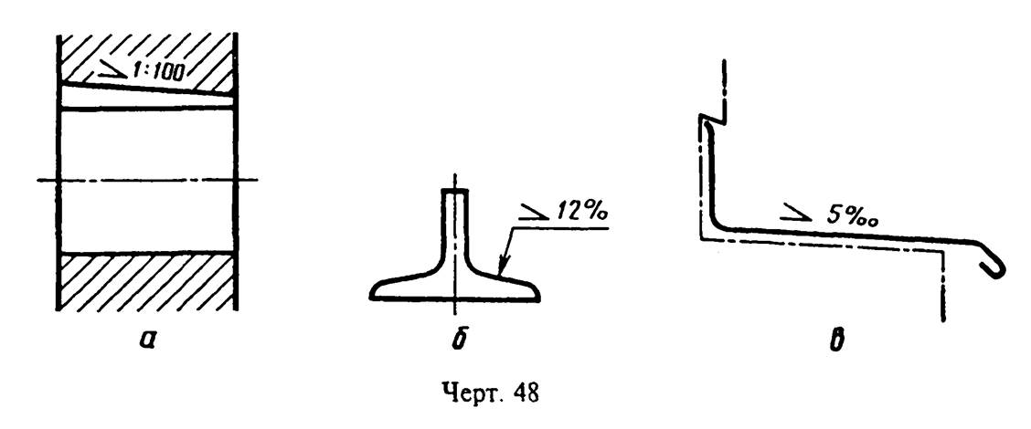
"Drawing 48. Designation of the slope of the surface"
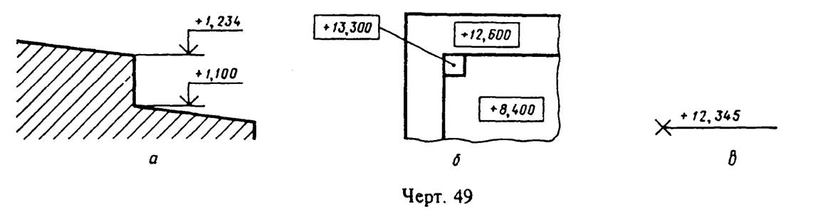
2.42. Level marks (heights, depths) of a structure or its element
from any reference level taken as "zero" in the form and
section, placed on extension lines (or on contour lines) and
denoted by the sign "│" made by solid thin lines, the length
strokes 2 - 4 mm at an angle of 45 ° to the extension line or contour line
(Fig. 49a), in the top view they should be applied directly in the frame
on the image or on the leader line (Fig. 49b), or as shown in
"Drawing 49. Designation of level marks (height, depth) of a structure or its element"
Level marks are indicated in meters with an accuracy of the third decimal place, without indicating the unit of measurement.
2.43. The dimensions of the chamfers at an angle of 45 ° are applied as shown in Fig. 50.
It is allowed to indicate the dimensions of a chamfer not shown in the drawing at an angle of 45 °, the size of which on the scale of the drawing is 1 mm or less, on the shelf of the leader line drawn from the face (Fig. 50a).
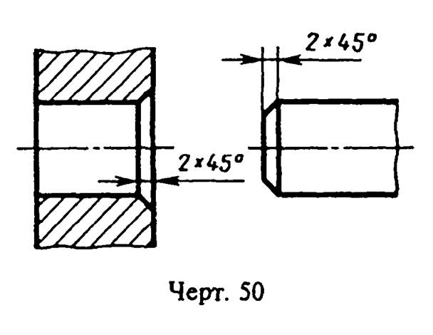
"Drawing 50. Applying chamfer dimensions"
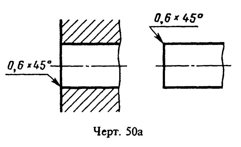
"Drawing 50a. Designation of a chamfer not shown in the drawing, the size of which is 1 mm or less on the scale of the drawing, on the shelf of the leader line drawn from the face"
The dimensions of the chamfers at other angles are indicated by general rules- linear angular dimensions (Fig. 51a and b) or two linear dimensions (Fig. 51c).
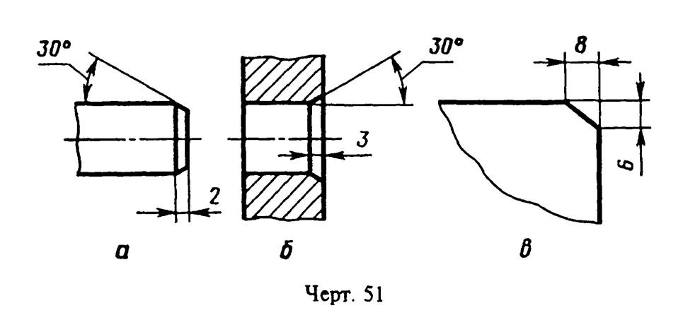
"Drawing 51. Designation of chamfer dimensions with linear angular dimensions or two linear dimensions"
2.40 - 2.43. (Changed edition, Rev. N 2).
2.44. The dimensions of several identical elements of the product, as a rule, are applied once, indicating the number of these elements on the shelf of the leader line (Fig. 52a).
It is allowed to indicate the number of elements, as shown in Figure 52b.
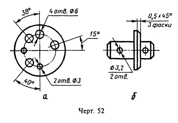
"Drawing 52. Dimensioning several identical elements of the product"
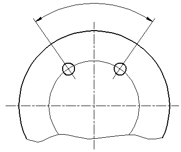
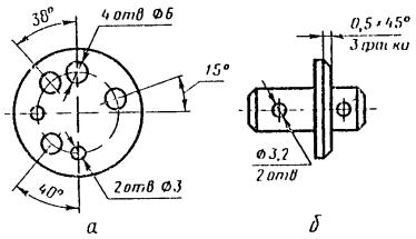
2.45. When applying the dimensions of elements evenly spaced around the circumference of the product (for example, holes), instead of the angular dimensions that determine the relative position of the elements, only their number is indicated (Fig. 53 - 55).
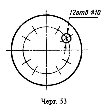
"Drawing 53. Dimensioning elements evenly spaced around the circumference of the product"

"Drawing 54. Dimensioning elements evenly spaced around the circumference of the product"

"Drawing 55. Dimensioning elements evenly spaced around the circumference of the product"
2.46. The dimensions of two symmetrically located elements of the product (except holes) are applied once without indicating their number, grouping, as a rule, all dimensions in one place (Fig. 56 and 57).
The number of identical holes is always indicated in full, and their dimensions - only once.
(Changed edition, Rev. N 2).
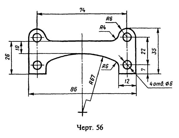
"Drawing 56. Dimensioning two symmetrically located elements of the product"
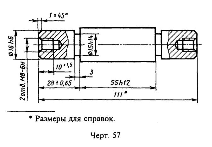
"Drawing 57. Dimensioning two symmetrically located elements of the product"
2.47. When applying dimensions that determine the distance between uniformly spaced identical elements of the product (for example, holes), it is recommended that instead of dimensional chains, apply the size between adjacent elements and the size between the extreme elements in the form of the product of the number of gaps between the elements by the size of the gap (Fig. 58).
2.47a. It is allowed not to apply on the drawing the dimensions of the radius of the arc of a circle of mating parallel lines (Fig. 58a).
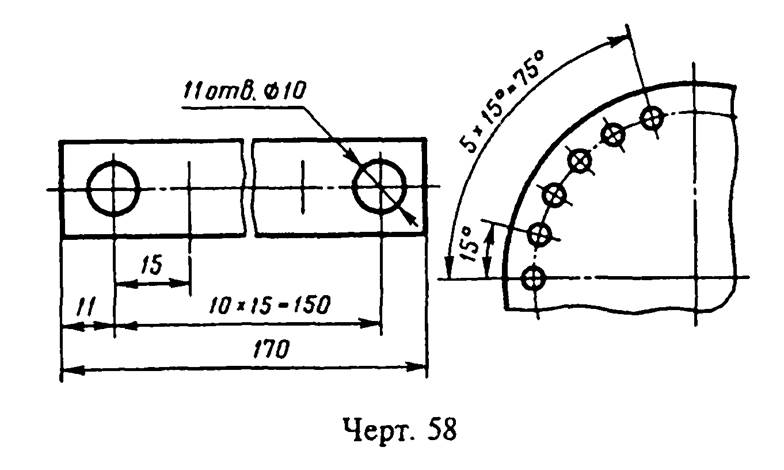
"Drawing 58. Applying dimensions that determine the distance between evenly spaced identical elements of the product"

"Drawing 58a. An example of not drawing on the drawing the dimensions of the radius of the arc of a circle of mating parallel lines"
(Introduced additionally, Rev. N 2).
2.48. At in large numbers dimensions applied from a common base, it is allowed to apply linear and angular dimensions, as shown in drawings 59 and 60, while drawing a common dimension line from the "0" mark and dimension numbers are applied in the direction of extension lines at their ends.
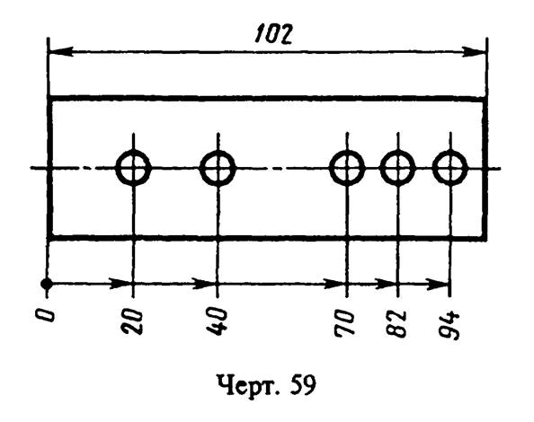
"Drawing 59. Drawing linear and angular dimensions with a large number of dimensions applied from a common base"
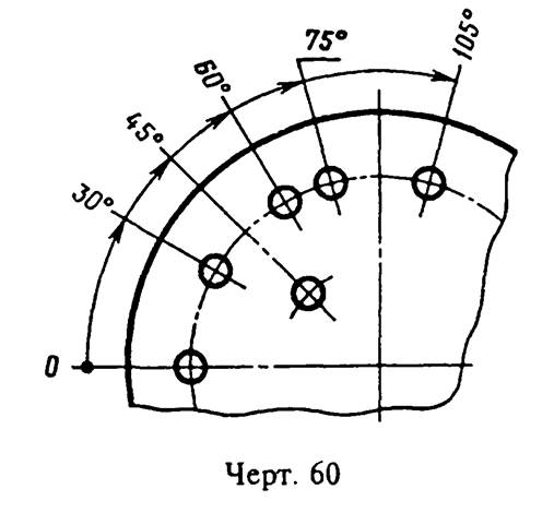
"Drawing 60. Drawing linear and angular dimensions with a large number of dimensions applied from a common base"
2.48a. The dimensions of the diameters of a cylindrical product of a complex configuration can be applied, as shown in drawing 60a.
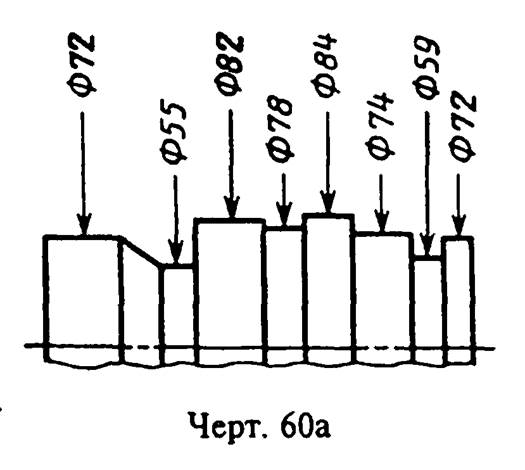
"Drawing 60a. Drawing the dimensions of the diameters of a cylindrical product of complex configuration"
(Introduced additionally, Rev. N 2).
2.49. With a large number of the same type of elements of the product, unevenly located on the surface, it is allowed to indicate their dimensions in the summary table, while using the coordinate method of drawing holes with the designation of their Arabic numerals(Fig.61) or the designation of the same type of elements capital letters(Fig. 61a).

┌──────────────────────┬────────────────────────┬───────────────────────┐
│Designation of holes │ Qty. │ Size, mm │
│ A │ 2 │ 3 │
├──────────────────────┼────────────────────────┼───────────────────────┤
│ B │ 4 │ 6.5 │
└──────────────────────┴────────────────────────┴───────────────────────┘
"Drawing 61. Designation of dimensions with a large number of the same type of product elements unevenly located on the surface"
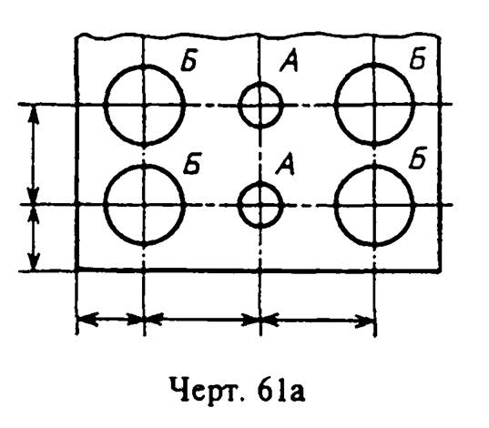
"Drawing 61a. Designation of dimensions with a large number of the same type of product elements unevenly located on the surface"
2.50. Identical elements located in different parts products (for example, holes) are considered as one element if there is no gap between them (Fig. 62a) or if these elements are connected by thin solid lines (Fig. 62b).
In the absence of these conditions, the total number of elements is indicated (Fig. 62c).
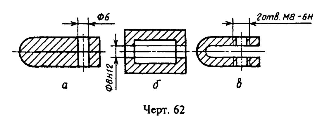
"Drawing 62. Consideration of identical elements located in different parts of the product"
2.51. If the same elements of the product (for example, holes) are located on different surfaces and shown in different images, the number of these elements is recorded separately for each surface (Fig. 63).
It is allowed to repeat the dimensions of the same elements of the product or their groups (including holes) lying on the same surface, only if they are significantly removed from each other and are not linked by sizes (Fig. 64 and 65).
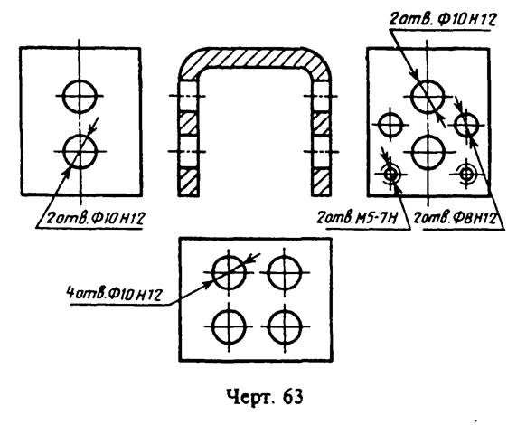
"Drawing 63. Designation of the number of identical elements of the product located on different planes and shown in different images"

Drawing 64
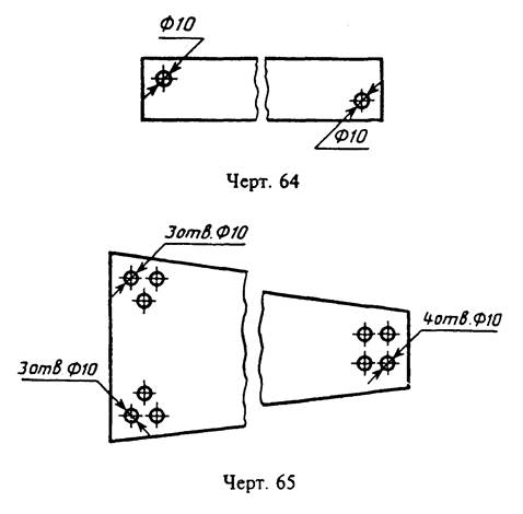
Drawing 65
2.49 - 2.51. (Changed edition, Rev. N 2).
2.52. If the drawing shows several groups of holes that are similar in size, then it is recommended to mark the same holes with one of the symbols shown in Fig. 66. Other symbols may also be used.
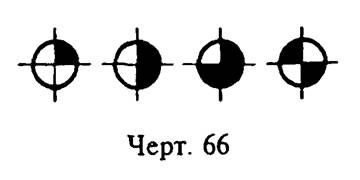
"Drawing 66. Designation in the drawing of several groups of similar-sized holes"
Holes denote conventional signs on the image that shows the dimensions that determine the position of these holes.
On construction drawings, it is allowed to outline the same groups of holes with a solid thin line with an explanatory inscription.
2.53. When designating identical holes with conventional signs, the number of holes and their sizes can be indicated in the table (Fig. 67).
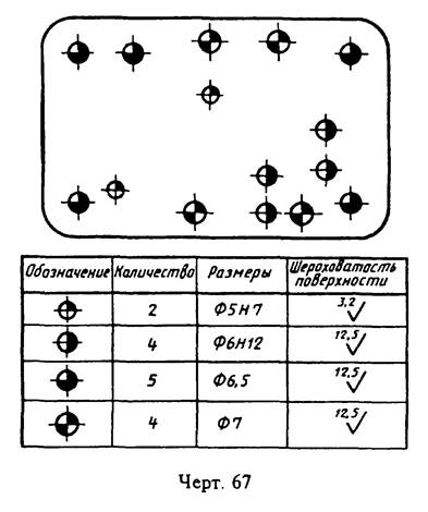
"Drawing 67. Designation of identical holes with conventional signs"
(Changed edition, Rev. N 2).
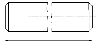
2.54. When depicting a part in one projection, the size of its thickness or length is applied, as shown in Fig. 68.

"Drawing 68. Applying the size of the thickness or length of the part shown in one projection"
2.55. The dimensions of a part or hole of a rectangular section can be indicated on the shelf of the leader line with the dimensions of the sides through the multiplication sign. In this case, in the first place, the size of that side of the rectangle from which the leader line is drawn should be indicated (Fig. 68a).
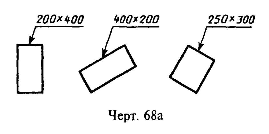
"Drawing 68a. Placing the dimensions of a part or hole of a rectangular section on the shelf of the leader line with the dimensions of the sides through the multiplication sign"
(Changed edition, Rev. N 2).
Application of limit deviations of dimensions
3.1. Limit deviations of dimensions should be indicated immediately after the nominal dimensions. Limit deviations of linear and angular dimensions of relatively low accuracy may not be indicated immediately after the nominal dimensions, but stipulated by a general entry in the technical requirements of the drawing, provided that this entry unambiguously determines the values and signs of the maximum deviations.
A general record of maximum deviations of dimensions with unspecified tolerances must contain symbols for maximum deviations of linear dimensions in accordance with GOST 25346 (for deviations in quality) or in accordance with GOST 25670 (for deviations in accuracy classes). Symmetrical limit deviations assigned by qualification should be designated + - IT / 2 indicating the number of the qualification.
The designations of one-sided limit deviations for qualifications assigned only for round holes and shafts (option 4 according to GOST 25670) are supplemented with a diameter sign (Dia.).
Examples of general records corresponding to options according to GOST 25670 for grade 14 and (or) accuracy class "average" are given in Table 1:
Table 1
───────────┬─────────────────────────────────────────────────────────────
Number │ Sample entry symbols
option │
───────────┼─────────────────────────────────────────────────────────────
1. │ H14, h14, +- t_2/2 or H14, h14, +- IT14/2
2. │ + t_2, -t_2, +- t_2/2
3. │ +- t_2/2 or +- IT14/2
4. │Dia. H14, Diam. h14, +- t_2/2 or Diam. H14, Diam. h14, +-
Notes:
1. It is allowed to supplement entries about unspecified limit deviations of dimensions with explanatory words, for example, "Unspecified limit deviations of dimensions H14, h14, + - t_2/2".
2. If the technical requirements in the drawing consist of one paragraph containing a record of unspecified maximum deviations of dimensions, or this entry is given in text documents, then it must be accompanied by explanatory words, for example, "Unspecified maximum deviations of dimensions + - t_2/2".
(Changed edition, Rev. N 2).
3.1a. The unspecified limit deviations of the radii of roundings, chamfers and corners are not specified separately, but must correspond to those given in GOST 25670 in accordance with the quality or accuracy class of the unspecified limit deviations of linear dimensions.
If all limit deviations of linear dimensions are indicated immediately after the nominal dimensions (there is no general record), then the unspecified limit deviations of the radii of roundings, chamfers and corners must correspond to those given in GOST 25670 for grades from 12 to 16 and are not specified in the drawing.
(Introduced additionally, Rev. N 2).
3.2. Limit deviations of linear dimensions are indicated on the drawings by symbols of tolerance fields in accordance with GOST 25346, for example: 18H7, 12e8 or numerical values, for example: 18 (+0.018) 12 (-0.032) _ (-0.059), or symbols of tolerance fields with indicating on the right in brackets their numerical values, for example: 18H7 (+0.018), 12e8 ((-0.032) _ (-0.059)).
It is allowed to indicate the numerical values of the limit deviations in the table (Table 2), located in the free field of the drawing.
When specifying nominal dimensions letters tolerance fields must be indicated after the dash, for example, D - H11.
table 2
───────────────────────┬─────────────────────────────────────────────────
Size │ Prev. off
───────────────────────┼─────────────────────────────────────────────────
18Н7 │ +0.018
12e8 │ -0.032
3.3. When indicating the maximum deviations with symbols, it is also necessary to indicate their numerical values in the following cases:
a) when assigning limit deviations (established by standards for tolerances and fits) of sizes not included in the series of normal linear dimensions according to GOST 6636, for example: 41.5 H7 (+0.025);
b) when assigning limit deviations, the symbols of which are not provided for in GOST 25347, for example, for a plastic part with limit deviations in accordance with GOST 25349 (Fig. 69);
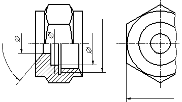
c) when assigning limit deviations for the dimensions of ledges with an asymmetric tolerance field (Fig. 70, 71);
d) (Deleted, Rev. N 2).
3.4. Limit deviations of angular dimensions are indicated only by numerical values (Fig. 72).
3.5. When recording limit deviations with numerical values, the upper deviations are placed above the lower ones. Limit deviations equal to zero are not indicated, for example: 60(+0.014)_(-0.032); 60(-0.100)_(-0.174); 60(+0.19); 60_0.19.
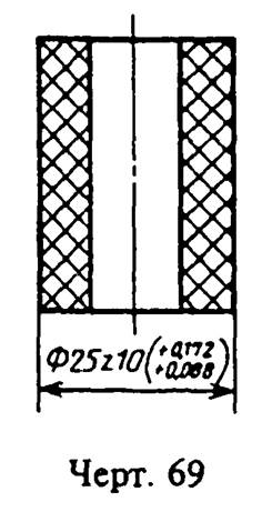
"Drawing 69. Designation of limit deviations with symbols and numerical values"
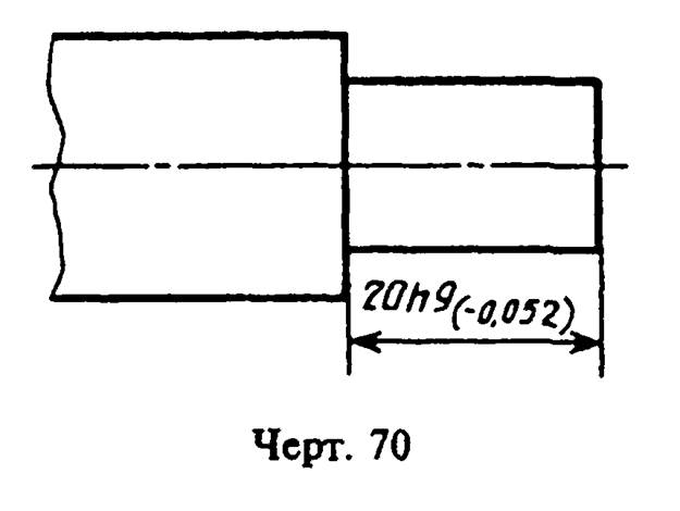
"Drawing 70. Application of maximum deviations in the dimensions of ledges with an asymmetric tolerance field"

"Drawing 71. Application of maximum deviations in the dimensions of ledges with an asymmetric tolerance field"
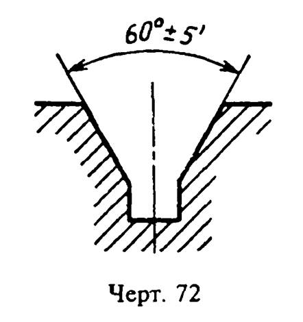
"Drawing 72. Designation of limit deviations of angular dimensions only with numerical values"
With a symmetrical arrangement of the tolerance field absolute value deviations are indicated once with a +- sign; in this case, the height of the digits defining the deviations must be equal to the height of the font of the nominal size, for example: 60 + - 0.23.
3.6. Limit deviations indicated by numerical values expressed decimal, write down to the last significant figure inclusive, equalizing the number of characters in the upper and lower deviations by adding zeros, for example: 10(+0.15)_(-0.30); 35(-0.080)_(-0.142).
3.7. Limit deviations of the dimensions of the parts shown in the assembly drawing are indicated in one of the following ways:
a) in the form of a fraction, in the numerator of which indicate the symbol of the hole tolerance field, and in the denominator - the symbol of the shaft tolerance field, for example:
50 ─── or 50H11/h11 (Drawing 73a);
b) in the form of a fraction, in the numerator of which indicate the numerical values of the maximum deviations of the hole, and in the denominator - the numerical values \u200b\u200bof the maximum deviations of the shaft (Fig. 73b);
b_1) in the form of a fraction, in the numerator of which indicate the symbol of the tolerance field of the hole, indicating on the right in brackets its numerical value, and in the denominator - the symbol of the shaft tolerance field with an indication of its numerical value in brackets on the right (Fig. 73c);

"Drawing 73. Designation of maximum deviations in the dimensions of the parts shown in the assembly drawing"
c) in the form of a record in which the maximum deviations of only one of the mating parts are indicated. In this case, it is necessary to explain to which part these deviations relate (Fig. 74).
3.8. When different limit deviations are assigned for surface sections with the same nominal size, the boundary between them is drawn with a solid thin line, and the nominal size is indicated with the corresponding limit deviations for each section separately (Fig. 75).
The boundary line between the sections should not be drawn through the shaded part of the image (Fig. 75a).

"Drawing 74. Designation of the maximum deviations of the dimensions of the parts shown in the assembly drawing, in the form of a record in which the maximum deviations of only one of the mating parts are indicated"

"Drawing 75. Drawing a boundary for surface sections with the same nominal size and different limit deviations"
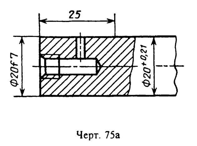
"Drawing 75a. Drawing a border line through the shaded part of the image"
3.2 - 3.8. (Changed edition, Rev. N 2).
3.9. If it is necessary to limit fluctuations in the size of identical elements of one part within a part of the tolerance field (Fig. 76a) or it is necessary to limit the amount of the accumulated error in the distance between repeating elements (Fig. 76b), then these data are indicated in the technical requirements.

"Drawing 76. Designation of data for limiting fluctuations in the size of identical elements of one part within a part of the tolerance field or limiting the amount of accumulated error in the distance between repeating elements"
3.10. When it is necessary to specify only one limit size (the second is limited upward or downward by some condition), after the size number indicate max or min, respectively (Fig. 77).

"Drawing 77. Designation of one limiting size, when the second is limited upward or downward by some condition"
It is also allowed to indicate the maximum dimensions on assembly drawings for gaps, tightness, backlash, etc., for example: "Make sure the axial displacement of the cam is within 0.6 - 1.4 mm."
3.11. Limit deviations of the location of the axes of the holes can be specified in two ways:
a) positional tolerances of the axes of the holes in accordance with the requirements of GOST 2.308;
b) limit deviations of the dimensions coordinating the axes (Fig. 78 - 80).

"Drawing 78. The maximum deviations of the location of the axes of the holes are indicated by the maximum deviations of the dimensions coordinating the axes
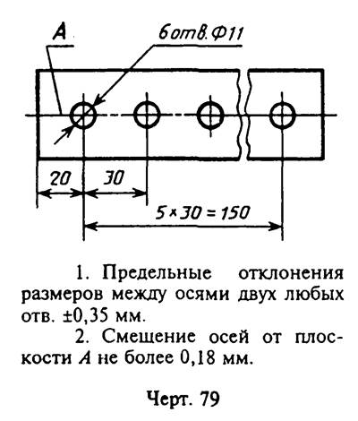
"Drawing 79. Limit deviations of the location of the axes of the holes are indicated by the limit deviations of the dimensions coordinating the axes"
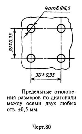
"Drawing 80. Limit deviations of the location of the axes of the holes are indicated by the limit deviations of the dimensions coordinating the axes"
If the tolerances for the location of the axes are dependent, then after the maximum deviations of the dimensions coordinating the axes, the sign of the dependent tolerance (M) should be indicated.
(Changed edition, Rev. N 2).
In order to rationally apply and correctly read the dimensions, it is necessary to study some of the conventions established by GOST 2.307-68 "Application of dimensions and maximum deviations". Consider some of the main provisions of this standard and recommendations of reference and educational literature:
Primary requirements
Dimensioning
Application of limit deviations
|
Primary requirements |
To determine the size of the depicted product and its elements, the dimensional numbers printed on the drawing are used.
The exception is the cases provided for in GOST 2.414-75; GOST 2.417-78; GOST 2.419-68, when the size of the product or its elements is determined from images made with a sufficient degree of accuracy.
The required accuracy of the product during manufacture is specified by indicating on the drawing the maximum deviations of dimensions, as well as the maximum deviations of the shape and location of surfaces.
The total number of dimensions in the drawing should be minimal, but sufficient for the manufacture and control of the product.
Reference dimensions in the drawing are marked with a “*”, and in the technical requirements they write: “* Dimensions for reference”. If all the dimensions in the drawing are for reference, they are not marked with a “*” sign, but in the technical requirements they write: “Dimensions for reference”.
On the drawings of products for dimensions, the control of which is technically difficult; put the sign "*", and in the technical requirements they put the inscription "Dimensions of providing. instr.". The indicated inscription means that the fulfillment of the size specified by the drawing with the maximum deviation must be guaranteed by the size of the tool or the corresponding technological process.
It is not allowed to repeat the dimensions of the same element in different images, in technical requirements, in the main inscription and in the specification. The exception is the reference dimensions (transferred from the drawings of blanks, the dimensions of parts (elements) from long, shaped, sheet and other rolled products).
If in the technical requirements it is necessary to refer to the size printed on the image, then this size or the corresponding element is indicated by a letter, and in the technical requirements an entry similar to that shown on figure 1.
|
The linear dimensions and their marginal deviations in the drawings and specifications are indicated in millimeters, without indicating the unit of measurement. If the dimensions on the drawing must be indicated not in millimeters, but in other units of measurement (centimeters, meters, etc.), then the corresponding dimensional numbers are recorded with the designation of the unit of measurement (cm, m) or indicated in the technical requirements. For dimensions and maximum deviations given in the technical requirements and explanatory inscriptions on the drawing field, the units of measurement must be indicated. Angular dimensions and limit deviations of angular dimensions are indicated in degrees, minutes and seconds with the designation of the unit of measurement, for example: 4 °; 4°30´; 12°50´30´´; 0°30´40´´; 0°18'; 0°5´25´´; 0°0´30´´; 30°±1°; 30°±10´. |
For dimensional numbers, simple fractions are not allowed, with the exception of sizes in inches.
The dimensions that determine the location of the mating surfaces are affixed, as a rule, from the structural bases, taking into account the possibilities of performing and controlling these dimensions.
When the elements of the object (holes, grooves, teeth, etc.) are located on the same axis or on the same circle, the dimensions that determine their relative position are applied in the following ways:
From a common base (surface, axes) - fig. 2a And b;
By setting the sizes of several groups of elements from several common bases - fig.3;
By setting dimensions between adjacent elements (chain) - fig.4.
Dimensions on the drawings are not allowed to be applied in the form of a closed chain, unless one of the dimensions is indicated as a reference.
Dimensions that determine the position of symmetrically located surfaces of symmetrical products are applied as shown in the figures. 5 And 6 .
For all dimensions printed on the working drawings, limit deviations are indicated.
It is allowed not to indicate limit deviations:
a) for dimensions that define zones of different roughness of the same surface, heat treatment zones, coating, finishing, knurling, notches, as well as diameters of knurled and notched surfaces. In these cases, the sign ≈ is applied directly to such dimensions;
b) for the dimensions of the parts of products of a single production set with an allowance for fit.
On such drawings, in the immediate vicinity of the indicated dimensions, the sign "*" is applied, and in the technical requirements they indicate:
“* Sizes with a fit allowance up to det. ……..”,
“* Dimensions with an allowance for fit according to hell. ……..”,
"*Dimensions with an allowance for fit on the mating part."
|
Dimensioning |
For drawing dimensions, extension and dimension lines and dimension numbers are used ( fig.7).
Dimension and extension lines should be made with solid thin lines. Dimension lines are limited by arrows. The size of the arrows is selected depending on the thickness S of the line of the visible contour of the object ( fig.8) and should be approximately the same for all dimension lines of the drawing.
When applying the size of a straight segment, the dimension line is drawn parallel to this segment, and the extension lines are perpendicular to the dimensions ( rice. nine). When dimensioning parts like the one shown in Figure 10, dimension lines should be drawn in the radius direction, and extension lines along the arcs of circles.
|
Figure 11. An example of applying the size of the corner |
When applying the size of an angle, the dimension line is drawn in the form of an arc with a center at its vertex, and extension lines are drawn radially ( rice. eleven). When applying dimensions, it must be remembered that all drawings, regardless of scale, indicate the actual dimensions of the product. Dimensional numbers within one drawing are performed in a font of the same size. Dimensional numbers are applied above the dimension line as close as possible to its middle. When drawing several parallel or concentric dimension lines at a small distance from each other, it is recommended to place the dimension numbers above them in a checkerboard pattern ( fig.16). When applying the size of the diameter inside the circle, the dimension numbers are shifted relative to the middle of the dimension lines. Dimensional numbers of linear dimensions with different slopes of dimension lines are arranged as shown in figure 12. If it is necessary to apply a dimension in the shaded area, the corresponding dimension number is applied on the shelf of the leader line ( fig.13). |
Angular dimensions are applied as shown in figure 14. In the zone located above the horizontal center line, the dimension numbers are placed above the dimension lines from the side of their convexity; in the area located below the horizontal center line - from the side of the concavity of the dimension lines. It is not recommended to apply dimensional numbers in the shaded area. In this case, the dimensional numbers indicate on the horizontally applied shelves ( fig.15).
|
Figure 16 Dimensioning Requirements |
The arrows limiting the dimension lines should rest with their tip against the corresponding contour lines, or extension, or axial lines. The extension lines should extend beyond the ends of the dimensional arrows by 1 ... 5 mm ( fig.16). The minimum distance between parallel dimension lines should be 7 mm, and between the dimension line and the contour line - 10 mm and are selected depending on the size of the image and the saturation of the drawing ( fig.16). In the cases shown in Figure 17, dimension and extension lines are drawn so that they, together with the measured segment, form a parallelogram. Avoid crossing dimension and extension lines. It is not allowed to use contour lines, axial, center and extension lines as dimension lines. It is allowed to draw dimension lines directly to the lines of the visible contour, axial, center and other lines. |

|
Figure 18. An example of applying a dimension with a broken dimension line |
Extension lines are drawn from the line of the visible contour, except for cases when, when applying dimensions on an invisible contour, there is no need to draw an additional image. If a view or section of a symmetrical object or individual symmetrically located elements is depicted only up to the axis of symmetry or with a break, then the dimension lines related to these elements are drawn with a break, and the break of the dimension line is made further than the axis or break line of the object ( fig.18). Dimension lines can be drawn with a break in the following cases: a) when specifying the size of the diameter of the circle, regardless of whether the circle is shown in whole or in part, while the break of the dimension line is done further than the center of the circle ( rice. 19); b) when applying dimensions from a base not shown in this drawing ( rice. twenty). |
|
Figure 19. An example of drawing the diameter of a circle |
Figure 20. An example of applying a dimension from a base not shown in this drawing |
|
Figure 21. Dimensioning when depicting a product with a gap |
When depicting a product with a break, the dimension line is not interrupted ( rice. 21) If the length of the dimension line is insufficient to place arrows on it, then the dimension line continues to be extended beyond the extension lines (or, respectively, beyond the contour, axial, center, etc.) and the arrows are applied, as shown in fig.22. If there is not enough space for arrows on dimension lines located in a chain, it is allowed to replace the arrows with serifs applied at an angle of 45 ° to the dimension lines or clearly marked points. If there is not enough space for an arrow due to a closely spaced contour or extension line, the latter can be interrupted. If there is not enough space above the dimension line to write the dimension number, then the dimensions are applied as shown in fig.23; if there is not enough space for drawing arrows, then they are applied, as shown in rice. 24. The method of applying the dimension number at different positions of the dimension lines (arrows) in the drawing is determined by the greatest ease of reading. |
|
Figure 22. An example of drawing dimension lines |
|
Figure 27. Applying dimensions related to the same structural element |
Dimensions related to the same structural element (groove, protrusion, hole, etc.) are recommended to be grouped in one place, placing them on the image in which the geometric shape of this element is shown most fully ( rice. 27). When drawing a radius dimension, a capital letter R is placed in front of the dimension number. If, when applying the size of the radius of an arc of a circle, it is necessary to specify the size that determines the position of its center, then the latter is depicted as an intersection of center or extension lines. With a large radius, the center can be brought closer to the arc, in this case the dimension line of the radius is shown with a break at an angle of 90 ° (Fig. 28). If it is not required to specify the dimensions that determine the position of the center of the circular arc, then the dimension line of the radius may not be brought to the center and shifted relative to the center (Fig. 29). |

When drawing several radii from one center, the dimension lines of any two radii are not located on the same straight line (Fig. 30a). If the centers of several radii coincide, their dimension lines may not be brought to the center, except for the extreme ones (Fig. 30b).
The dimensions of the radii of the outer fillets are applied as shown in rice. 31, internal fillets - on rice. 32.
Rounding radii, the size of which is 1 mm or less on the scale of the drawing, are not shown in the drawing and their dimensions are applied as shown in rice. 33.
The method of applying dimensional numbers at different positions of the dimension lines (arrows) in the drawing is determined by the greatest readability. The dimensions of the same radii are allowed to be indicated on a common shelf, as shown in rice. 34.
If the radii of fillets, bends, etc. are the same throughout the drawing or some radius is predominant, then instead of drawing the dimensions of these radii directly on the image, it is recommended to make an entry in the technical requirements like: “Rounding radii 4 mm”; "Internal bending radii 10mm"; "Unspecified radii 8 mm", etc.
When specifying the size of the diameter (in all cases), the sign "Æ" is applied before the size number.
Before the dimension number of the diameter (radius) of the sphere, the sign Æ (R) is also applied without the inscription "Sphere" ( fig.35).
|
Figure 35. An example of applying the size of a sphere |
If it is difficult to distinguish a sphere from other surfaces in the drawing, then before the dimension number of the diameter (radius) it is allowed to put the word "Sphere" or the sign "○", for example, "Sphere Æ 18, ○R12". The diameter of the sign of the sphere is equal to the size of the dimensional numbers in the drawing.
The dimensions of the square are applied as shown in Figure 36. The height of the sign "" must be equal to the height of the dimensional numbers in the drawing.
|
|
|
|
|
Figure 36. An example of applying the size of a square |
||


Before the dimension number characterizing the taper, the sign "" is applied, the acute angle of which should be directed towards the top of the cone ( rice. 37).
|
Figure 37. An example of applying the size of the taper |

The sign of the cone and the taper in the form of a ratio should be applied above the center line or on the shelf of the leader line.
The slope of the surface should be indicated directly at the image of the slope surface or on the shelf of the leader line in the form of a ratio ( rice. 38a), in percents ( rice. 38b) or in ppm ( rice. 38v). Before the dimension number that determines the slope, a “>” sign is applied, the acute angle of which should be directed towards the slope.
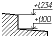
Level marks (heights, depths) of a structure or its element from any reference level, taken as "zero" in the view and section, are placed on extension lines (or on contour lines) and denoted by the sign "↓" made by solid thin lines, length of strokes 2-4 mm at an angle of 45 ° to the extension line or contour line ( rice. 39a), in the top view they should be applied in a frame directly on the image or on the leader line ( rice. 39b), or as shown in figure 39c. Level marks are indicated in meters with an accuracy of the third decimal place without indicating units of measurement.
|
|
| |
|
Figure 39. An example of applying a level mark |
||

The dimensions of the chamfers at an angle of 45 ° are applied as shown in fig.40a.
It is allowed to indicate the dimensions of a chamfer not shown in the drawing at an angle of 45 °, the size of which on the scale of the drawing is 1 mm or less, on the shelf of the leader line drawn from the face ( rice. 40b).
The dimensions of the chamfers at other angles are indicated according to the general rules - linear and angular dimensions ( rice. 41 a and b) or two linear dimensions ( rice. 41c).
The dimensions of several identical elements of the product, as a rule, are applied once, indicating the number of these elements on the shelf of the leader line ( rice. 42a). You can specify the number of elements, as shown in rice. 42 b.
When applying the dimensions of elements that are evenly spaced around the circumference of the product (for example, holes), instead of the angular dimensions that determine the relative position of the elements, only their number is indicated ( rice. 43 a B C).
The dimensions of two symmetrically located elements of the product (except holes) are applied once without indicating their number, grouping, as a rule, in one place all dimensions ( rice. 44 And 45 ). The number of identical holes is always indicated in full, and their dimensions - only once.
DIMENSIONING
AND MAXIMUM DEVIATIONS
GOST 2.307-68
(ST SEV 1976-79, ST SEV 2180-80)
STATE STANDARD OF THE UNION OF THE SSR
|
one system design documentation APPLICATION OF DIMENSIONS AND MAXIMUM DEVIATIONS Unified system for design documentation. |
GOST (ST SEV 1976-79, |
Introduction date 01.01.71
This standard establishes the rules for applying dimensions and limit deviations on drawings and other technical documents for products of all industries and construction.
1. BASIC REQUIREMENTS
The exception is the cases provided for in GOST 2.414-75; GOST 2.417-78; GOST 2.419-68, when the size of the product or its elements is determined from images made with a sufficient degree of accuracy.
The basis for determining the required accuracy of the product during manufacture is the maximum deviations of dimensions indicated on the drawing, as well as the maximum deviations of the shape and location of surfaces.
1.2. The total number of dimensions in the drawing should be minimal, but sufficient for the manufacture and control of the product.
1.3. Dimensions that are not subject to execution according to this drawing and are indicated for greater ease of use of the drawing are called reference.
1.4. Reference dimensions in the drawing are marked with a “*”, and in the technical requirements they write: “* Dimensions for reference”. If all dimensions on the drawing are for reference, they are not marked with an “*”, but in the technical requirements they write: “Dimensions for reference”.
On construction drawings, reference dimensions are noted and specified only in cases provided for in the relevant documents approved in the prescribed manner.
a) one of the sizes of a closed dimensional chain. Limit deviations of such dimensions are not indicated in the drawing (dev.);
___________
* Dimensions for reference.
Heck. one
b) dimensions transferred from the drawings of blank products (dev.);
___________
* Dimensions for reference.
Heck. 2
c) dimensions that determine the position of the elements of the part to be processed on another part (Fig.);
___________
1* Dimensions for reference.
2** Process according to the mating part (or according to detail ...).
Heck. 3
d) dimensions on the assembly drawing, which determine the limiting positions of individual structural elements, for example, piston stroke, valve stem stroke of an internal combustion engine, etc.;
e) dimensions on the assembly drawing, transferred from the drawings of parts and used as installation and connecting ones;
e) overall dimensions on the assembly drawing, transferred from the drawings of parts or being the sum of the dimensions of several parts:
g) the dimensions of parts (elements) from sectional, shaped, sheet and other rolled products, if they are fully determined by the designation of the material given in column 3 of the main inscription.
Notes:
1. The reference dimensions specified in subparagraphs b, c, d, f, g of this paragraph can be applied both with and without maximum deviations
2. Installation and connecting dimensions are called, which determine the dimensions of the elements by which this product is installed at the installation site or attached to another product.
3. Dimensional dimensions are those that determine the limiting external (or internal) outlines of the product.
1.6. On the drawings of products for dimensions, the control of which is technically difficult; put the sign "*", and in the technical requirements they put the inscription "Dimensions of providing. instr.".
Note. The indicated inscription means that the fulfillment of the size specified by the drawing with the maximum deviation must be guaranteed by the size of the tool or the corresponding technological process.
At the same time, the dimensions of the tool or the technological process are checked periodically in the process of manufacturing products.
The frequency of control of the tool or the technological process is established by the manufacturer together with the customer's representative.
1.7. It is not allowed to repeat the dimensions of the same element in different images, in technical requirements, in the main inscription and in the specification. The exception is the reference dimensions given in paragraph b and well.
If in the technical requirements it is necessary to refer to the size printed on the image, then this size or the corresponding element is indicated by a letter, and in the technical requirements an entry similar to that shown in the figure is placed. .

___________
1. Tolerance of parallelism of the axes holes. BUT And B 0.05 mm.
2. Size difference IN on both sides no more than 0.1 mm.
Heck. 4
Dimensions may be repeated on construction drawings.
1.5-1.7.
1.8. Linear dimensions and their maximum deviations in the drawings and specifications are called in millimeters, without indicating the unit of measurement.
For dimensions and maximum deviations given in the technical requirements and explanatory inscriptions on the drawing field, the units of measurement must be indicated.
(Revised edition, Rev. No. 3).
1.9. If the dimensions on the drawing must be indicated not in millimeters, but in other units of measurement (centimeters, meters, etc.), then the corresponding dimensional numbers are recorded with the designation of the unit of measurement (cm, m) or indicated in the technical requirements.
On construction drawings, units of measurement in these cases may not be indicated if they are specified in the relevant documents approved in the prescribed manner.
1.10. Angular dimensions and limit deviations of angular dimensions are indicated in degrees, minutes and seconds with the designation of the unit of measurement, for example - 4 °; 4°30 " ; 12°45 " 30" ; 0°30 " 40" ; 0 ° 18" ; 0 ° 5" 25" ; 0°0 " 30" ; 30°± l°; 30°±10 " .

Heck. five
Heck. 6
1.11. For dimensional numbers, simple fractions are not allowed, with the exception of sizes in inches.
1.12. The dimensions that determine the location of the mating surfaces are affixed, as a rule, from the structural bases, taking into account the possibilities of performing and controlling these dimensions.
1.13. When the elements of the object (holes, grooves, teeth, etc.) are located on the same axis or on the same circle, the dimensions that determine their relative position are applied in the following ways:
from a common base (surface, axis) - according to hell. a and b;
setting the sizes of several groups of elements from several common bases - according to hell. in;
setting the dimensions between adjacent elements (chain) - according to hell. .
1.14. Dimensions on the drawings are not allowed to be applied in the form of a closed chain, except when one of the dimensions is indicated as a reference (see Fig.).
On construction drawings, dimensions are applied in the form of a closed chain, except as provided for in the relevant documents approved in the prescribed manner.
Dimensions that determine the position of symmetrically located surfaces of symmetrical products are applied as shown in Fig. And .
Heck. 7
___________
* Dimensions for reference.
Heck. 8
(Revised edition, Rev. No. 2).
1.15. For all dimensions printed on the working drawings, limit deviations are indicated.
It is allowed not to indicate limit deviations:
a) for dimensions that define zones of different roughness of the same surface, heat treatment zones, coating, finishing, knurling, notches, as well as diameters of knurled and notched surfaces. In these cases, a sign is applied directly to such dimensions » ;
b) for the dimensions of the parts of products of a single production set with an allowance for fit.
On such drawings, in the immediate vicinity of the indicated dimensions, the sign "*" is applied, and in the technical requirements they indicate:
“* Sizes with a fit allowance up to det. . . . . ",
“* Dimensions with an allowance for fit according to hell. . . . . ",
"*Dimensions with an allowance for fit, according to the mating part."
On construction drawings, the maximum deviations of dimensions are indicated only in cases provided for in the relevant documents approved in the prescribed manner.
1.16. When making working drawings of parts manufactured by casting, stamping, forging or rolling, followed by machining of a part of the surface of the part, indicate no more than one size in each coordinate direction, connecting the machined surfaces with surfaces not subjected to machining (Fig. and).
Heck. nine
Heck. 10
(Revised edition, Rev. No. 2).
1.17. If the element is depicted with a deviation from the scale of the image, then the dimension number should be underlined (Fig. a).

Heck. 10a
2. DIMENSIONING
2.1. Dimensions in the drawings are indicated by dimensional numbers and dimension lines.
2.2. When applying the size of a straight segment, the dimension line is drawn parallel to this segment, and the extension lines are perpendicular to the dimension lines (Fig.).

Heck. eleven
2.3. When applying the size of an angle, the dimension line is drawn in the form of an arc with a center at its vertex, and extension lines are drawn radially (Fig.).
Heck. 12
2.4. When drawing the size of an arc of a circle, the dimension line is drawn concentric to the arc, and the extension lines are parallel to the bisector of the angle, and the sign "Ç " (heck. ).
Heck. 13
It is allowed to place the extension lines of the arc dimension radially, and if there are still concentric arcs, it is necessary to indicate to which arc the dimension belongs (Fig.).
Heck. fourteen
2.4a. When applying the dimensions of parts similar to those shown in Fig. a, dimension lines should be drawn in the radial direction, and extension lines - along the arcs of circles (Fig. a).
![]()
Heck. 14a
(Introduced additionally, Amendment No. 2).
2.5. The dimension line at both ends is limited by arrows resting on the corresponding lines, except for the cases given in paragraphs. , , and , and when drawing a radius line bounded by an arrow on the side of the defined arc or fillet.
On construction drawings, instead of arrows, it is allowed to use serifs at the intersection of dimension and extension lines, while the dimension lines should protrude beyond the extreme extension lines by 1. . . 3 mm.
2.6. In the cases shown in Fig. , dimension and extension lines are drawn so that they, together with the measured segment, form a parallelogram.
Heck. 15
2.7. It is allowed to draw dimension lines directly to the lines of the visible contour, axial, center and other lines (Fig. and).
Heck. 16

Heck. 17
2.8. Dimension lines are preferably drawn outside the outline of the image.
2.9. The extension lines must extend beyond the ends of the arrowheads of the dimension line by 1 . . 5 mm.
2.10. The minimum distance between parallel dimension lines should be 7 mm, and between the dimension line and the contour line - 10 mm and are selected depending on the size of the image and the saturation of the drawing.
(Revised edition, Rev. No. 2).
2.11. It is necessary to avoid the intersection of dimension and extension lines (see Fig.).
2.12. It is not allowed to use contour lines, axial, center and extension lines as dimension lines.
2.13. Extension lines are drawn from the lines of the visible contour, except for the cases specified in paragraphs. and , and cases when, when dimensioning on an invisible contour, there is no need to draw an additional image.
a) when specifying the size of the diameter of the circle, regardless of whether the circle is shown in whole or in part, while the break of the dimension line is done further than the center of the circle (Fig.);
Heck. twenty
b) when applying dimensions from a base not shown in this drawing (Fig.).
Heck. 21
2.18. When depicting a product with a gap, the dimension line is not interrupted (Fig.).
Heck. 22
2.19. The values of the elements of the arrows of the dimension lines are selected depending on the thickness of the lines of the visible contour and are drawn approximately the same throughout the drawing. The shape of the arrow and the approximate ratio of its elements are shown in Fig. .
Heck. 23
(Revised edition, Rev. No. 2).

Heck. 43b
If the radii of fillets, bends, etc. are the same throughout the drawing or some radius is predominant, then instead of drawing the dimensions of these radii directly on the image, it is recommended to make an entry in the technical requirements like: “Rounding radii 4 mm”; "Internal bending radii 10 mm"; "Unspecified radii 8 mm", etc.
2.35, 2.36. (Revised edition, Rev. No. 2).
2.37. When specifying the size of the diameter (in all cases), the sign "Æ ».
2.38. Before the dimension number of the diameter (radius) of the sphere, a sign is also appliedÆ (R) without the inscription "Sphere" (damn). If it is difficult to distinguish a sphere from other surfaces in the drawing, then before the dimension number of the diameter (radius) it is allowed to put the word “Sphere” or the sign O, for example, “SphereÆ 18, OR12".
The diameter of the sign of the sphere is equal to the size of the dimensional numbers in the drawing.

Heck. 44
2.39. The dimensions of the square are applied as shown in Fig. , and a.
![]()
Heck. 45
Heck. 46
Heck. 46a
The height of the sign □ must be equal to the height of the dimension numbers in the drawing.
2.38, 2.39 (Revised edition, Rev. No. 2).
2.40. Before the dimension number characterizing the taper, put the sign "< ", the acute angle of which should be directed towards the top of the cone (Fig.).
Heck. 47
The sign of the cone and the taper in the form of a ratio should be applied above the center line or on the shelf of the leader line.
2.41. The slope of the surface should be indicated directly at the image of the slope surface or on the shelf of the leader line in the form of a ratio (fig. a), in percent (fig. b) or in ppm (fig. c). Before the dimension number that determines the slope, put the sign "< ”, the acute angle of which should be directed towards the slope.
Heck. 48
2.42. Level marks (heights, depths) of a structure or its element from any reference level, taken as "zero" in the view and section, are placed on extension lines (or on contour lines) and are marked with the sign "¯ ”, made with solid thin lines, the length of the strokes is 2 - 4 mm at an angle of 45 ° to the extension line or contour line (Fig. a), in the top view they should be applied in a frame directly on the image or on the leader line (Fig. b) , or as shown in hell. but.

Heck. 49
Level marks are indicated in meters with an accuracy of the third decimal place without indicating the unit of measurement.
2.43. The dimensions of the chamfers at an angle of 45 ° are applied, as shown in Fig. .

Heck. fifty
It is allowed to indicate the dimensions of a chamfer not shown in the drawing at an angle of 45 °, the size of which on the scale of the drawing is 1 mm or less, on the shelf of the leader line drawn from the face (Fig. a).
Heck. 50a
The dimensions of the chamfers at other angles are indicated according to the general rules - linear and angular dimensions (Fig. a and b) or two linear dimensions (Fig. c).
Heck. 51
2.40-2.43. (Revised edition, Rev. No. 2).
2.44. The dimensions of several identical elements of the product, as a rule, are applied once, indicating the number of these elements on the shelf of the leader line (Fig. a).
It is allowed to specify the number of elements, as shown in Fig. b.
Heck. 52
2.45. When applying the dimensions of elements evenly spaced around the circumference of the product (for example, holes), instead of angular dimensions that determine the relative position of the elements, only their number is indicated (Fig. -).
Heck. 53
Heck. 54

Heck. 55
2.46. The dimensions of two symmetrically located elements of the product (except for holes) are applied once without indicating their number, grouping, as a rule, all dimensions in one place (Fig. and).
Heck. 56
___________
* Dimensions for reference.
Heck. 57
The number of identical holes is always indicated in full, and their dimensions - only once.
(Revised edition, Rev. No. 2).
2.47. When applying dimensions that determine the distance between evenly spaced identical elements of the product (for example, holes), it is recommended that instead of dimensional chains, apply the size between adjacent elements and the size between the extreme elements in the form of the product of the number of gaps between the elements by the size of the gap (Fig.).
Heck. 58
2.47a. It is allowed not to apply in the drawing the dimensions of the radius of the arc of a circle of mating parallel lines (Fig. a).
Heck. 58a
(Introduced additionally, Amendment No. 2).
2.48. With a large number of dimensions applied from a common base, it is allowed to apply linear and angular dimensions, as shown in Fig. and, at the same time, a common dimension line is drawn from the “0” mark and the dimension numbers are applied in the direction of the extension lines at their ends.

Heck. 59
Heck. 60
2.48a. The dimensions of the diameters of a cylindrical product of complex configuration can be applied, as shown in Fig. but.
Heck. 60a
(Introduced additionally, Amendment No. 2).
2.49. With a large number of the same type of elements of the product, unevenly located on the surface, it is allowed to indicate their sizes in the summary table, while using the coordinate method of making holes with their designation in Arabic numerals (Fig.), or designation of the same type of elements in capital letters (Fig. a).
Heck. 61
Heck. 61a
|
Hole designation |
Size, mm |
|
2.50. Identical elements located in different parts of the product (for example, holes) are considered as one element if there is no gap between them (Fig. a) or if these elements are connected by thin solid lines (Fig. b).
In the absence of these conditions, the total number of elements is indicated (fig. c).
Heck. 62
2.51. If the same elements of the product (for example, holes) are located on different surfaces and are shown in different images, then the number of these elements is recorded separately for each surface (Fig.).

Heck. 63
It is allowed to repeat the dimensions of the same elements of the product or their groups (including holes) lying on the same surface, only if they are significantly removed from each other and are not linked by dimensions (Fig. and).
Heck. 64

Heck. 65
2.49-2.51. (Revised edition, Rev. No. 2).
2.52. If the drawing shows several groups of similarly sized holes, it is recommended to mark the same holes with one of the symbols shown in Fig. . Other symbols may also be used.
Heck. 66
The holes are indicated by symbols on the image, which shows the dimensions that determine the position of these holes.
On construction drawings, it is allowed to outline the same groups of holes with a solid thin line with an explanatory inscription.
2.53 When designating identical holes with conventional signs, the number of holes and their sizes may be indicated in the table (Fig.).
Heck. 67
(Revised edition, Rev. No. 2).
2.54. When depicting a part in one projection, the size of its thickness or length is applied, as shown in Fig. .

Heck. 68
2.55. The dimensions of a part or hole of a rectangular section can be indicated on the shelf of the leader line with the dimensions of the sides through the multiplication sign. In this case, in the first place, the size of that side of the rectangle from which the leader line is drawn should be indicated (fig. a).
Heck. 68a
(Revised edition, Rev. No. 2).
3. APPLICATION OF DIMENSIONAL DEVIATIONS
A general record of the maximum deviations of dimensions with unspecified tolerances must contain symbols for the maximum deviations of linear dimensions in accordance with GOST 25346-89 (for deviations by quality) or according to GOST 25670-83 (for deviations, by accuracy classes). Symmetrical limit deviations, assigned by qualifications, should be denoted indicating the qualification number.
Designations of one-sided limit deviations for qualifications assigned only for round holes and shafts (option 4 according to GOST 25670-83) are supplemented with a diameter sign (Æ ).
Examples of general records corresponding to options according to GOST 25670-83 for grade 14 and (or) accuracy class "average" are given in Table. :
Table 1
|
Legend notation example |
|
|
H 14, h 14 or H 14, h 14, |
|
|
+t2, -t2, |
|
|
Æ H 14, Æ h 14 or Æ H 14, Æ h 14, |
Notes:
1. It is allowed to supplement entries on unspecified maximum deviations of dimensions with explanatory words, for example, “Unspecified maximum deviations of dimensions: H 14, h fourteen, ".