How to remake a lampshade for LED lamps. Converting a fluorescent lamp to an LED lamp. Conversion of a lamp with electronic ballast
PWM brightness controller on MK ATmega8, battery-powered, and charge indication.
The article is intended for persons with some knowledge of radio electronics, namely:
- what is a microcontroller and how to flash it,
- what is PWM regulation,
- what is a led driver.
The project was designed to be installed on a bicycle. How it all began. My friends and I often took part in night bike rides, so we needed a headlight for our bike. Well, I didn’t want to install a regular flashlight... I needed something more functional. For example, with brightness adjustment “low / medium / maximum”, and since it was planned to use a lithium-ion battery as power supply, a charge level indicator was also needed. I saw many similar projects on the Internet, but somehow they did not suit me. For example, I came across projects for PWM brightness controllers, but they either did not have a charge level indicator, or the charge level indicator was on 1...3 LEDs, and I did not like such little information content. Well, do it like that, and I set about assembling my project. So, as a charge indicator, I take 10 LEDs, or rather, I take an LED “column”, like this:
I ordered this LED “bollard” from an online store (there are no radio stores in our city), so it will arrive only in a couple of weeks. Instead, I temporarily installed 10 regular LEDs.
I used ATmega8 (or ATmega328) as the control microcontroller, since this MK has an ADC, with which I organized the measurement of the battery charge level. This MK also has a sufficient number of pins (and we want to connect as many as 10 LEDs). This microcontroller is common in radio stores, and is relatively cheap - in the range of 50...100 rubles, depending on the greed of the store and the type of case.

To understand how the device works, let's look at the block diagram:

This article describes only what concerns the PWM controller (the left side of the block diagram), and you choose the LED driver and the LED itself to your taste, the one that suits you best. The ZXSC400 driver suits me, so I will use it as an example.
The PWM controller must be connected to an LED driver that has a dimming function (DIM, PWM, etc.), such as the ZXSC400. You can use any other suitable driver, as long as it supports PWM brightness control and is powered by the same battery that powers the PWM controller. For those who do not know what an LED driver is, I’ll explain: a driver is needed so that the LED glows equally brightly both when the battery is charged and when the battery is dead. In other words, the LED driver maintains a stable current through the LED.

Typical circuit diagram for switching on the ZXSC400 LED driver:

The power of this circuit must be connected to the power of our PWM regulator, and the PWM output from the regulator must be connected to the “STDN” input of the ZXSC400 driver. The “STDN” pin is used to adjust the brightness using a PWM signal. In a similar way, you can connect the PWM controller to many other LED drivers, but that's a separate topic.
Algorithm of device operation. When power is applied, the MK displays the battery charge level for 1 second (on an LED scale of 10 LEDs), then the LED scale goes off, the MK goes into energy saving mode and waits for control commands. I made all the controls on one button in order to pull fewer wires on the bike. When you hold the button for more than 1 second, the PWM controller turns on, and a signal with a duty cycle of 30% (1/3 of the LED brightness) is supplied to the PWM output. When you press the button again for more than 1 second, the PWM controller turns off, and no signal is supplied to the PWM output (0% duty cycle). When you briefly press the button, the brightness switches from 30% - 60% - 100%, and the battery charge is displayed for 1 second. Thus, a single press changes the brightness of the LED, and a long press turns the LED on/off. To test the functionality of the PWM controller, I connected a regular LED to its output, but I repeat once again - solely for the purpose of testing functionality. In the future I will connect the PWM controller to the ZXSC400 driver. The operation of the device is shown in more detail and clearly in the video (link at the end of the article).
The following diagram also shows the process of adjusting brightness:

What to do if you are not satisfied with these brightness values? For example, you want it to be like this: 1%, then 5%, then 100%. I have provided for this option as well. Now the user can set these three brightness values to whatever he wants! To do this, I wrote a small program that, based on the desired values, generates a file for flashing the EEPROM. Flashing into the microcontroller this file, the brightness will change accordingly to the desired ones. I am attaching a screenshot of the program window:

If you do not flash the EEPROM file, the brightness values will remain “default” - 30%, 60%, 100%. A correctly assembled device does not require configuration. If desired, you can only adjust the minimum, average, and maximum brightness at your discretion. The program and instructions for use are at the end of the article.
Selecting the battery to use. I used a Li-ion battery due to its prevalence and low cost. But in the circuit I included jumper J1, with which you can select what we use as power.

If jumper J1 is in position “1”, then one Li-ion battery is used. If jumper J1 is in position “2”, then three ordinary AAA/AA/C/D batteries are used, connected in series. Jumper J1 is necessary to correctly display the battery charge level, since Li-ion battery the operating voltage is approximately in the range of 3.3...4.2V, and for conventional batteries the operating voltage is approximately 3.0...4.5V. I have attached tables of battery voltages with indicator readings at the bottom of the article.
Indicator LEDs. The LEDs that display the battery charge level can be anything. You can adjust their brightness within small limits by changing the value of the current-limiting resistor R1. To display the charge level, a dynamic indication is used, thanks to which energy savings are achieved, since only one LED is lit at a time. You can also watch the video about indicating the battery charge level (link at the end of the article).

The microcontroller can be either ATmega8 or ATmega328. Both of these microcontrollers are compatible in the arrangement of contacts, and differ only in the content of the “firmware”. I used ATmega328 because I had this MK in stock. In order to reduce power consumption, the microcontroller is powered by an internal 1 MHz RC oscillator. The microcontroller program is written in environment 4.3.6.61 (or 4.3.9.65).
The circuit uses a TL431 reference voltage source microcircuit. With its help, good accuracy in measuring battery voltage is achieved. Power is supplied to TL431 from the PC1 pin of the microcontroller through resistor R3. The supply voltage to the TL431 occurs only during the charge level indication. After the indication LEDs go out, the supply voltage is stopped, saving battery energy. The TL431 chip can be found in unusable power supplies from computers, in broken chargers from cell phones, V pulse blocks power supply from laptops and various electronic equipment. I used the TL431 in a SOIC-8 package (smd version), but the TL431 is more common in a TO-92 package, so I made several PCB variations.

About emulation in the program " ". The project in Proteus is not working correctly. Due to the fact that the ATmega8 model does not wake up from sleep mode, and also with brakes, a dynamic indication is displayed. If, after starting the project, you immediately hold the button so that the PWM controller turns on, then everything works. But as soon as you hold down the button again to turn off the PWM controller, the MK will go into sleep and will not wake up again (until the project is restarted). I am not attaching the project in Proteus. Who wants to play around - write, I will send the project to Proteus.
Main technical characteristics:
- Supply voltage at which operation is guaranteed: 2.8 ... 5 volts
- PWM signal frequency: 244 Hz
- Dynamic display frequency of a scale of 10 LEDs: 488 Hz (per 10 LEDs) or 48.8 Hz (per LED)
- Number of brightness modes switchable in a cycle: 3 modes
- The user can change the brightness of each mode: Yes
Below you can download firmware for MK ATmega8 and ATmega328
Shutov Maxim, Velsk
List of radioelements
| Designation | Type | Denomination | Quantity | Note | Shop | My notepad | |
|---|---|---|---|---|---|---|---|
| U1 | MK AVR 8-bit | ATmega8-16PU | 1 | To notepad | |||
| U2 | Voltage reference IC | TL431ILP | 1 | To notepad | |||
| Resistors | |||||||
| R1, R2 | Constant resistor SMD 1206 | 330 Ohm | 2 | To notepad | |||
| R3 | Constant resistor SMD 1206 | 1 kOhm | 1 | To notepad | |||
| R4 | Constant resistor SMD 1206 | 10 kOhm | 1 | To notepad | |||
| R5 | Constant resistor SMD 1206 | 47 kOhm | 1 | To notepad | |||
| Constant resistor SMD 1206 | |||||||
Rich Rosen, National Semiconductor
Introduction
The exponential growth in the number of LED light sources is accompanied by an equally rapid expansion of the range of integrated circuits designed to control LED power. Switching LED drivers have long replaced power-hungry linear regulators, which were unacceptable for a world concerned with energy savings, becoming the de facto standard for the industry. Applications ranging from hand-held flashlights to stadium signage require precise control of stabilized current. In this case, it is often necessary to change the intensity of LED radiation in real time. Controlling the brightness of light sources, and LEDs in particular, is called dimming. This article outlines the basics of LED theory and describes the most popular dimming methods using switching drivers.
LED brightness and color temperature
LED brightness
The concept of brightness of the visible set emitted by an LED is quite easy to understand. Numeric value The perceived brightness of an LED's emission can be easily measured in units of surface luminous flux density called candela (cd). The total power of light emitted by an LED is expressed in lumens (lm). It is also important to understand that the brightness of the LED depends on average size direct current.
Figure 1 shows a graph of the luminous flux of a certain LED versus forward current. In the range of used values of forward currents (I F), the graph is extremely linear. Nonlinearity begins to appear as I F increases. When the current leaves the linear section, the efficiency of the LED decreases.
| Picture 1. | |
When operating outside the linear region, a significant portion of the power supplied to the LED is dissipated as heat. This wasted heat overloads the LED driver and complicates the design's thermal design.
LED color temperature
Color temperature is a parameter characterizing the color of the LED and is indicated in the reference data. The color temperature of a particular LED is described by a range of values and shifts with changes in forward current, junction temperature, and also as the device ages. The lower the color temperature of the LED, the closer its glow is to the red-yellow color, called “warm”. Blue-green colors, called “cool” colors, correspond to higher color temperatures. Often for color LEDs, instead of a color temperature, a dominant wavelength is specified, which can shift just like the color temperature.
Ways to control the brightness of LEDs
There are two common ways to control the brightness (dimming) of LEDs in circuits with switching drivers: pulse width modulation (PWM) and analog regulation. Both methods ultimately come down to maintaining a certain level average current through an LED, or a chain of LEDs. Below we will discuss the differences between these methods and evaluate their advantages and disadvantages.
Figure 2 shows a switching LED driver circuit in a buck converter configuration. The voltage V IN in such a circuit must always exceed the sum of the voltages on the LED and resistor R SNS. The inductor current flows entirely through the LED and resistor R SNS, and is regulated by the voltage supplied from the resistor to the CS pin. If the voltage at the CS pin begins to fall below the set level, the duty cycle of the current flowing through L1, the LED, and R SNS increases, causing the average LED current to increase.
Analogue dimming
Analog dimming is cycle-by-cycle control of the direct current of an LED. In simple terms, this is maintaining the LED current at a constant level. Analog dimming is accomplished either by adjusting the current sense resistor R SNS or by changing the DC voltage level applied to the DIM pin (or similar pin) of the LED driver. Both examples of analog control are shown in Figure 2.
Analog dimming with R SNS control
From Figure 2 it is clear that for a fixed reference voltage At the CS pin, a change in the value of R SNS causes a corresponding change in the LED current. If it were possible to find a potentiometer with a resistance of less than one ohm that could withstand high LED currents, this dimming method would have a right to exist.
Analogue dimming via supply voltage control via CS pin
More the hard way involves direct cycle-by-cycle control of the LED current using the CS pin. To do this, in a typical case, a voltage source taken from the LED current sensor and buffered by an amplifier is included in the feedback loop (Figure 2). To adjust the LED current, you can control the gain of the amplifier. It is easy to add additional functionality to this feedback circuit, such as current and temperature protection.
The disadvantage of analog dimming is that the color temperature of the light emitted can be affected by the forward current of the LED. In cases where changing the color of the glow is unacceptable, LED dimming by direct current regulation cannot be used.
Dimming using PWM
Dimming using PWM consists of controlling the moments of turning on and off the current through an LED, repeated at a fairly high frequency, which, taking into account the physiology of the human eye, should not be less than 200 Hz. Otherwise, a flickering effect may occur.
The average current through the LED now becomes proportional to the duty cycle and is expressed by:
I DIM-LED = D DIM × I LED
I DIM-LED - average current through the LED,
D DIM - duty cycle of PWM pulses,
I LED - rated current of the LED, set by choosing the resistance value R SNS (see Figure 3).
 |
|
| Figure 3. | |
LED Driver Modulation
Many modern LED drivers have a special DIM input to which PWM signals can be supplied over a wide range of frequencies and amplitudes. The input provides a simple interface with external logic circuits, allowing you to turn the converter output on and off without delays in restarting the driver, without affecting the operation of other components of the chip. A number of additional functions can be implemented using the output enable pins and auxiliary logic.
Two-wire PWM dimming
Two-wire PWM dimming has gained popularity in automotive interior lighting circuits. If the voltage at the VINS pin becomes 70% less than the voltage at VIN (Figure 3), the internal power MOSFET is disabled and current through the LED is turned off. The disadvantage of this method is the need to have a PWM signal conditioner circuit in the converter power supply.
Fast PWM dimming with shunt device
The delay in the moments of turning the converter output on and off limits the PWM frequency and the range of change in the duty cycle. To solve this problem, you can connect a shunt device, such as, say, the MOSFET transistor shown in Figure 4a, in parallel with the LED, or string of LEDs, to quickly bypass the output current of the converter bypassing the LED(s).
 |
|
| A) | |
 |
|
| b) | |
| Figure 4. | Fast PWM dimming (a), current and voltage shapes (b). |
The inductor current remains continuous while the LED is turned off, due to which the rise and fall of the current is no longer delayed. Now the rise and fall times are limited only by the characteristics of the MOSFET transistor. Figure 4a shows a circuit diagram connecting a shunt transistor to an LED driven by an LM3406 driver, and Figure 4b shows waveforms illustrating the difference in results obtained when dimming using the DIM pin (top) and when connecting a shunt transistor (bottom). In both cases, the output capacitance was 10 nF. Shunt MOSFET transistor type .
When shunting the current of LEDs controlled by converters with current stabilization, one must take into account the possibility of current surges when the MOSFET transistor is turned on. The LM340x family of LED drivers feature converter turn-on timing to help address emissions issues. To save maximum speed switching on/off, the capacitance between the LED terminals should be minimal.
A significant disadvantage of fast PWM dimming, compared to the converter output modulation method, is the reduction in efficiency. When the shunt device is open, it dissipates power, which is released in the form of heat. To reduce such losses, you should choose MOSFET transistors with minimal open channel resistance R DS-ON.
Multi-mode dimmer LM3409
- The eye "tool" is good, but without "numerical" values. Only a spectrometer can show something specific. Link please. And do you seriously believe that something is being done outside of “China” (Asian countries)?
- Link please.
- =Vlad-Perm;111436][B]Vladimir_007 [B]"To extend the service life, several more LEDs are placed next to it (butt-to-end)"? - I have a lot of LEDs nearby to increase the total brightness........... I apologize, I ended up on this thread again by accident. Numbers 6 - 8 ago there was an article in the radio pilot where I also inserted my remark. It’s not modest to mention the quality of LED products; a couple of magazines ago, a motorist had an article on headlights about LED overheating. So 6 - 8 issues ago in the article there was a driver circuit, which is a garland switch for 4 channels. “thanks to the driver, we increase the service life of the LED by 4 times due to the fact that it works 4 times less often, also 2_th +, the duration of operation of the diode crystal with a graph exponentially increases the service life by reducing the temperature of the crystal” - approximately verbatim from memory . As for photographing headlights - LED is a strobe for the human eye, but with a very high speed
- switching and so far no one has boasted of an increase (afterglow) of the LED after a power failure.
- Dear [b]Vladimir_666, hello. Why did you decide this? When the LED is powered with direct current, a continuous stream of light radiation is formed. When powered with pulsed current, light pulses are formed. The LED [B] is inertialess. This remarkable property is widely used when transmitting digital information over optical fiber at speeds of tens of Gigabytes per second or more. It also requires an appropriate phosphor that does not create an afterglow. I think you understand this perfectly well. When talking about a strobe, you obviously mean individual quanta of light. But they have not yet learned how to use them separately. It is not clear who gave the downvote and why?
- [b] SATIR, you are partly grass in that [I] The LED is inertia-free. This is true for bare-chip LEDs. White LEDs developed for lighting have a layer of phosphor. And it has some afterglow time (several milliseconds), which is quite sufficient when powered by pulses with a frequency of kilohertz. In addition, a filter capacitor is installed in the drivers.
- Good afternoon. By the word strobe with high frequency, I meant exactly a strobe. If you take the glow of an ordinary light bulb with a maximum voltage of 220V and a minimum of 0 and this with a frequency of 50 Hz - the temperature of the filament at 220V is 2200 degrees, but when the voltage drops to 0 and rises again to 220V, the temperature of the filament does not fall to 0, but drops to 1500 - 1800 degrees, which is what we see “with the naked eye”. As for the LED, their operating principle is a strobe, with a high switching speed, which is not visible to the human eye, but this does not mean that it does not affect vision. As for data transfer gigabytes per second - usually data transfer is transmitted (in Morse code, a flashing light), I understand that a person would put (-), you can be stupid, if, according to people's reviews, you consider yourself to be just as smart - decide for yourself where You have a constantly burning light bulb and which of us needs to turn it on -.
- Well, like 50 Hz. These are two half-sine waves and actually blink at 100 Hz. and the amplitude voltage is about 300 V. Who told you this? Or where did you read this? Read about the principle of operation in Wik, but the topic seems to be about powering LEDs. A normal driver powers the LED constantly. PWM controllers are used only if you need to CHEAPLY reduce the brightness of the glow. Good driver, again, can reduce the current to the LED without using PWM. PWM is used in multi-mode flashlights - and if the driver is at least somewhat adequate, the PWM frequency is from several kHz. Completely unnoticeable during any use. Yeah, for me too, when the hard drive transmits data, the “light” (LED) blinks, blinks so quickly! She is the one transmitting the data!
- Don't touch Vladimir666. He doesn't understand how the LED works. And obviously he won't understand. He came up with an incorrect explanation for himself and pushes it to everyone left and right.
- All of the above is exactly the opposite
- ctc655 I think I explained to you in a clear form that a constantly burning light bulb cannot transmit information if you are trying to protect LED manufacturers with your backing track through your [B]unprofessional actions
- Thanks Vladimir666. My opinion of you has not improved. Alas. Even in childhood, about 38 years ago, they made a light telephone using a LIGHT BULB. It was powered by direct current. It worked. He conveyed information. Another thing is at what speed, so to speak. But your idea of how an LED works is nonsense. Either you have it as a spark gap or as a strobe light. Young people revere and then start talking nonsense. If it's hard to understand, don't bother. For this we received -1. This is an assessment of the informativeness of the message. Your messages not only are not informative, but also give an erroneous idea of the topic. Where there is no such big nonsense, I don’t put anything.
- Look at the topic on the same site to make it clear why again! http://www..php?p=199007#post199007 Discussion: Lighting devices based on LEDs alternating current find their niche and, perhaps, go beyond it. I’m also not 10 or 30 years old, but it will be useful for you to read. Increase knowledge in addition to a high-tech device with r-n transition. I wonder how you transmitted information 30 years ago with a light bulb burning on direct current? All lighting devices, no matter - optocoupler, optothyristor, etc. all work due to interruptions in the light flow. Perhaps a patent was created specifically for this?
- Justify or confirm. I am an “electronics engineer” - you don’t have to be limited in terminology. The fact that the driver (powered by 220 V.) operates according to the circuit AC (220 V.) - DC (300 V.) - AC PWM - DC (stable required current CC) - CC to the LED does not make it PWM regulator. (this can also be simply called a voltage rectifier!) PWM with feedback it's just one way to keep the LED brightness (current) stable. But you can adjust the brightness in two ways: in the specified chain in “AS PWM”, additionally introduce a “fill” adjustment (the LED will be powered by an adjustable stable current) or regulate the PWM directly [B] the average current per light. In the first case, it is powered by a stable current (no ripple!) In the second case, the LED is powered by “pulses” and they are, in principle, visible. (not necessarily with the eyes - in flashlights I have encountered frequencies of both 200 Hz and 9 kHz.) Using Morse code - is this not the transfer of information?
- To be honest, I don’t know why I need to confirm a known truth. Maybe, of course, there are some nuances in the development of adjustable drivers (and they should be). I haven't done this yet. Therefore, the methods of regulation you propose have the right to life. But each one is used in its own way. Regarding Morse code. Yes, this is the transfer of information, but with a break in the light flux. And that light telephone worked by changing the brightness of the light bulb without going out. In the absence of speech, the light was constantly on. I didn't find the diagram. We did it in a circle and didn’t yet have the habit of sketching diagrams. Also, some closed optocouplers, resistor for example, can operate without interrupting the light flow.
- Dear [b]ctc655, hello. [B]You are absolutely right. A similar method of sound transmission is still used in cinema. Along the edge of the film there is a light path that modulates the light flux, which is converted into an electrical signal. The method has existed since the invention of sound cinema! It was he who destroyed the tapers.
- I somehow forgot about this. Although it may be different now. Honestly, I haven’t been interested in cinema for a long time.
- I don’t argue that without the lights going out, the circuits can be different, from ordinary logic to 554CA..(3) comparators, you can just light the light bulb and pull the “flag” in front of the light bulb, but signal transmission has always worked by changing “1” and "0".
- On digital devices - yes. Do light level sensors also work when a light bulb or the sun goes out? Moreover, the illumination level is adjustable......
- The previous topic or dispute, if you read it, was about the transfer of data “supposedly with a constantly burning light bulb” from a direct current source, that is, a battery or a stabilized power source. (I don’t want to raise the topic - where does it end? AC voltage and the constant begins, since there is now a lot of controversy on this topic on the internet, starting with the battery itself.....) As for the level of illumination, are you talking about motion sensors or about night lighting, say, around store windows? It seems that in 1_x the light in the usual concept is a little inconsistent with the theme, but the principle is almost the same!
Thanks to the miniature size of LEDs, engineers have learned to create lamps of a wide variety of designs, including repeating the shape of fluorescent and halogen lamps. Tubular fluorescent lamps of the T8 type with a G13 socket were no exception. They can be easily replaced with a similar-shaped tube with LEDs, significantly improving the optical-energy characteristics of the existing lamp.
Is it necessary to change fluorescent light bulbs to LED lamps?
Today we can confidently say that LED light bulbs of any form factor are superior to their fluorescent counterparts in almost all respects. Moreover, LED technologies continue to progress, which means that products based on them will be even more advanced in the future. To confirm this, below is Comparative characteristics two types of tubular lamps.
T8 fluorescent lamps:
- MTBF is about 2000 hours and depends on the number of starts, but not more than 2000 cycles;
- light spreads in all directions, which is why they need a reflector;
- gradual increase in brightness at the moment of switching on;
- the ballast (ballast) serves as a source of network interference;
- degradation of the protective layer with a decrease in luminous flux by 30%;
- The glass flask and the mercury vapor inside it require careful handling and disposal.
T8 LED lamps:
Besides, LED bulbs T8 have twice the light output with equal power consumption, are less likely to fail and have a warranty from the manufacturer. Possibility of placement inside the flask different quantities LEDs allow you to achieve an optimal level of illumination. This means that instead of a T8-G13-600 mm 18 W fluorescent lamp, you can install a 9, 18 or 24 W LED lamp of the same length.
The abbreviation T8 indicates the diameter of the glass tube (8/8 inch or 2.54 cm), and G13 is the type of cap indicating the pin spacing in mm.
Having weighed all the pros and cons, we can conclude that converting a fluorescent lamp to an LED light bulb is completely justified, both from a technical and economic point of view.
Connection diagrams
Before moving on to upgrading the lamp with replacement fluorescent lamps T8 to LED, first you need to properly understand the circuits. All fluorescent lamps are connected in one of two ways:
In raster ceiling lamps, 4 fluorescent tubes are connected to 2 electronic ballasts, each of which provides operation of two lamps, or to a combined ballast, including 4 starters, 2 chokes and 1 capacitor.
The connection diagram for the T8 LED lamp does not contain any additional elements (Fig. 3).  A stabilized power supply (driver) for LEDs is already built inside the case. Along with it under a glass or plastic diffuser is printed circuit board with LEDs, mounted on an aluminum radiator. The 220V supply voltage can be supplied to the driver through the pins of the base, either on one side (usually on Ukrainian-made products) or on both sides. In the first case, the pins located on the other side serve as fasteners. In the second case, 1 or 2 pins can be used on each side. Therefore, before modifying the lamp, you need to carefully study the connection diagram shown on the LED lamp body or in its documentation.
The most common are T8 LED lamps with phase and neutral connections from different sides, so alteration of the lamp will be considered based on this option.
What needs to be changed?
- By carefully looking at the diagrams, even an inexperienced electrician will understand how to connect an LED lamp instead of a fluorescent one. In a luminaire with ballasts, you need to perform the following steps:
- Turn off the circuit breaker and make sure there is no voltage.
- Remove the protective cover, gaining access to the circuit elements.
- Remove the capacitor, inductor, and starter from the electrical circuit.
- Separate the wires going to the cartridge terminals and connect them directly to the phase and neutral wires.
- The remaining wires can be removed or insulated.
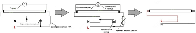
Insert a T8 G13 lamp with LEDs and perform a test run.
The contacts in the form of pins for connecting the T8 LED lamp are marked on its base with the symbols “L” and “N”.
Converting a fluorescent lamp with electronic ballast is even easier. To do this, just unsolder or cut with wire cutters the wires going to and from the ballast. Then connect the phase and neutral wires to the wires of the left and right sockets of the lamp. Insulate the connection point, insert an LED lamp and apply supply voltage. It is much easier to install and connect a T8 LED lamp in Philips branded lamps. simplified the task as much as possible for its consumers. To install an LED lamp with a length of 600 mm, 900 mm, 1200 mm or 1500 mm, you will need to unscrew the starter and screw in the plug supplied in the kit in its place. In this case, there is no need to disassemble the lamp body and remove the choke.
When choosing a T8 G13 LED lamp, you should pay attention to the design of the base. It can be rotary or have a rigid connection to the body. Models with a rotating base are considered to be the most universal. They can be screwed into any converted light fixture, with either vertical or horizontal slots in the socket. And by adjusting the angle of the lamp, you can change the direction of the light flux.
It is not uncommon to find negative reviews on the Internet that the service life of T8 LED lamps is much less than stated. As a rule, such comments are left by people who bought a Chinese “no name” for the price of a fluorescent lamp. Naturally, the quality of the LEDs and drivers will not allow it to work even for one year.
Read also
I waited my turn for remodeling and this kitchen ceiling lamp. I recently changed energy-saving lamps to LEDs in the bathroom, and now I need to redo the chandelier in the kitchen. This lamp has two energy lamps with an E27 base, so instead of them you will need to stuff two sets of drivers and LEDs here. The difficulty is that all this LED technology simply loves to warm up and warm everything around it :-) And given that the lamp is ceiling-mounted and therefore poorly ventilated due to the glass hemisphere, there is a high probability that the LEDs will overheat, because the light in the kitchen sometimes burns for hours. Therefore, I immediately refused to install LEDs on the steel base of the lamp, although it is almost twice as large as those in the bathroom, but it is very thin, almost like a beer can.


Unscrew energy-saving lamps, disconnect the power wires from the ceiling terminal and remove the base of the lamp from the ceiling by unscrewing the three screws.

For the role of a passive radiator, I decided to adapt a sheet of duralumin approximately 2.5 mm thick. We get rid of the cartridges and measure the diameter of the lamp base.

In my case, the diameter of the pancake will be approximately 33cm. Using a compass, we beat out a circle on a sheet of aluminum, after which, using a jigsaw with a metal file, we cut out the future area for the LEDs. We clean the sawn nickel with sandpaper and get rid of burrs on the edges.


Next, we need to transfer the marks to it so that the LEDs are evenly installed in their places. So that the heat is evenly distributed throughout the metal, and the light does not shine anyhow. For this I used a paper stencil, which I pored over for almost an hour. You can ignore this point and glue the LEDs at random, as long as they don’t bunch up on the aluminum sheet. One hell, all this beauty will not be visible behind the lampshade.

I decided to lighten the front surface of the radiator. Therefore, I wrapped several layers of paper tape on the cardboard, as if putting it in a stack, and then I cut out these round pieces with a homemade punch (a piece of pipe with a sharpened end) and glued them to the previously made marks.


After painting the radiator with white paint, peel off the round pieces of tape and degrease the exposed areas with some kind of chemical, alcohol, vodka, solvent, acetone, etc.


The radiator is ready for gluing LEDs, but before that we make sure to call them with a tester, since sometimes we come across non-working (defective) ones. We also straighten the legs of the LEDs, because initially they are pressed closer to the base of the LED.

I tried to glue them in such a way that I could then connect them in series. Later it will be clear that I still screwed up with one LED, because I glued it on the wrong side and the wires to it had to be pulled in a roundabout way :-)

After drying for a day, we proceed to soldering all the LEDs in the circuit. The connection diagram is the same as in this homemade lamp, except that there are two drivers, and there are one more light bulbs in each circuit, because one of the drivers did not want to start with 10 LEDs ().


As soon as we have finished weaving the web, we connect the drivers and test turn on our spotlight. In my case, after an hour of continuous operation, the plate became slightly warm. True, the test is not entirely correct, since the LEDs look up, and besides, they are not covered by a glass dome. But in any case, such a large radiator does its job perfectly. By the way, I don’t recommend looking at the bright LEDs that are turned on without protecting your eyes with some kind of glasses, since the light is so bright that after it, dark pea spots remain in your eyes for a long time. Even cameras don't do well if you focus on LEDs. I suspect that such stress for the eyes obviously does not add sharpness to vision :-)

After the tests, we unsolder the drivers and placing them in the center of the spotlight, we make marks on the radiator. After that, we drill holes for the nylon ties, the terminal block and the supply of the network wire. It doesn’t hurt to remove the chamfers with a large drill so that nothing is rubbed or cut through.


We cut out a round insulator from some kind of plastic, the ideal would be textolite, but for some reason I couldn’t find it at home. We place it under the block, which we fasten with a screw, and then we tighten the drivers themselves with nooses. Finally, we solder and clamp the wires into place.

This is what all this disgrace looks like from the opposite side (photo below).


To attach the radiator to the base of the lamp, I had to drill three more holes around the perimeter, and then stupidly hang it on a wire (photo below). Although it would be more reasonable to tightly screw it through large washers in order to transfer heat to the base of the lamp.


Actually, here is another lamp placed on the meter, waiting for it to burn out completely or for some LED to burn out. Initially, there were two warm energy-saving lamps of 23 W each, but now there are 44 warm LEDs. The total power of this luminaire with two drivers is now approximately 27W. By eye, I didn’t notice any difference in brightness; I don’t have any sophisticated lux meters yet, but the mobile phone sensor from a distance of 170 cm shows almost same values, perhaps a few points less (photo above). In general, what are these homemade lamps They shine brightly and consume little, this is of course a big plus. But in this moment, I am more concerned not about saving energy, but about how long these garlands will last, since in Lately I want to gradually get off this expensive energy-saving needle :-)
Below I have listed some components from Ali for assembling a similar lamp.
Disassembly and modification of Chinese LED lamps
There are enough publications on our website dedicated to light sources. These are, first of all, incandescent lamps; here we have found a solution to protect them from burnout and extend their service life. Perhaps they still remain the most widespread source of light, and the reason here is not only accessibility, but also that the spectrum of their radiation is most pleasing to the eye. In addition to conventional light bulbs, so-called “energy saving” lamps - compact fluorescent lamps - are popular. We have provided a description of repair methods and modifications that also increase service life. However, LED light sources should also be considered as they are gaining popularity.
An LED lamp consists of several LEDs (or an LED matrix) with a power circuit contained in a base. Proper nutrition LEDs are a whole science, benefit of drivers mains power plenty has been invented, from specialized microcircuits to simple circuits on two transistors. However, manufacturers very rarely take advantage of the advances in circuit technology and modern electronics, preferring to power LEDs out of habit - through a ballast (quenching) capacitor.
For the study, three 3W LED lamps made in China were purchased at a price of 35 rubles per piece.

The body is made of plastic, the diffuser in the form of a hemisphere is also plastic, it is attached without glue, it simply snaps into place. To disassemble an LED lamp, just pry the diffuser in a circle and disengage it from the lamp body. This releases the printed circuit board with parts.

Two of the three lamps have one wire missing, otherwise the installation is more or less neat. Quenching capacitor marked 824 - 820 nF (0.82 µF), 400 V. 9 LEDs of a size similar to 3528, only thinner, connected in series. The bridge is assembled from four diodes marked M7.

One such lamp shines very weakly. With a lamp power of 3W, its light should be comparable to an incandescent lamp with a power of 20-25W. These lamps shine more dimly, which seems to hint to us at the need for measurement, which will be done soon, at the same time the need for improvement will be clarified - is there a significant current surge when turned on, do the LEDs work, as they say, “overheating”?

The LED lamp circuit is simple. As already mentioned, the LEDs are powered through a quenching capacitor.
Simulation shows that a current of 32mA flows through the LEDs, the total voltage drop across the chain of nine LEDs is 26V, so their power consumption is 0.8W, which is three times less than stated.
These lamps are sold as three-watt lamps. Of course they real power- three times less. Each lamp contains 10 2835 LEDs. Judging by the datasheets, these LEDs allow current up to 150mA with good heat dissipation. In this particular case, the whole thing is powered through a ballast capacitor with a capacity of 0.82 μF and a 100 ohm resistor connected in series. Shorting the resistor does not have a significant effect on the brightness of the glow. The lamps shine very dimly.

It can be disassembled by simply tilting the matte diffuser to the side. The LED board is secured with silicone glue.
The following modification was planned: to increase the capacity of the ballast capacitor in order to increase the current. For testing, a capacitor with a capacity of 1.5 μF was installed. In this case, the aluminum substrate of the LEDs became excessively hot. Therefore, modification of these lamps was impossible.
The following lamps are more honest products of Uncle Liao. The lamp is designed for 12 volt power supply (halogen power supplies). The case is also a radiator made of honest aluminum.

The lamps are made on the basis of 1-watt LEDs connected in series. Inside the base there is an ultra-compact stabilizer of who knows what, which (attention!) does not work. The brightness of the lamps varies depending on the supply voltage. And this despite the fact that the famous MC34063 and XL6001 are hidden under the heat shrink in one of the lamps.
It can be disassembled by unscrewing the top and bottom parts.
Possible alteration: convert to 220 volts and a “human” base. This requires alteration of the lamp design.
Processing of large corns. The lamps themselves are easy to disassemble - by removing the plastic ring at the end. It is fixed using small rods, some of which can be glued. They will have to be torn off. When the ring is removed, a round platform with LEDs will be released. Inside the lamp there is a small board with a capacitor ballast, on which an electrolytic capacitor with a capacity of 4.7 μF is installed. This capacity is clearly not enough for the given lamp power, resulting in flickering that is invisible to the eye. There is another, not obvious drawback: the small capacity of this electrolyte is an insufficient load for the capacitor ballast at the beginning of operation. As you know, a discharged capacitor has zero resistance and when the lamp is turned on, a voltage surge occurs, which may well burn out some LED. To protect against this unpleasant phenomenon, you should install a capacitor with a larger capacity, which will provide the necessary voltage drop when turned on, or shunt the LEDs with a zener diode. The second option is more complicated (you also need to find a zener diode at a relatively high voltage) and does not eliminate flicker, so the obvious modification is to install electrolytic capacitor larger capacity.

Initially, the payment is not received, because connected by short wires to the lamp base. Pushing it out as far as possible, we unsolder the wiring. It is quite possible to do this. We unsolder the 4.7 µF capacitor and install in its place a more capacitive one, in in this case- at 68 uF 450V. The space inside the lamp allows it to be installed with reverse side fees. We don’t install a zener diode yet - we drive the lamp like this.
Everything is collected in reverse order. It should also be remembered that a lamp with a capacitor ballast is galvanically connected to the network and is dangerous. Therefore, it will not be superfluous to glue or draw the appropriate symbols to avoid touching live parts. Actually, almost the entire lamp contains such parts. When installing or removing it, you need to hold it very carefully, using the plastic ring.