Structural elements of parts and products. Structural elements. Drawing
The process of designing a part consists in choosing a material, the shape of its surfaces and determining its dimensions. In addition, the designer must indicate the permissible deviations of the material characteristics, errors in the manufacture of dimensions and shapes, type of coatings, type of processing, technical and technological conditions and requirements (for example, nitriding, hardening, aging, etc.).
So, the design characteristics of the part: MATERIAL, SHAPE, DIMENSIONS.
The following are general aspects of these characteristics. More detailed overview given in the description of technological methods.
Material selection is made based on: functional purpose details; conditions of its operation; rational manufacturing technology; cost and scarcity of material; ergonomic and aesthetic requirements.
The designer is guided by the nomenclature, assortment and physical and mechanical properties of structural materials (Table 1).
For example, if a lens is designed, then its material must be transparent for the operating range of wavelengths of light. If the lens will be used in a tropical or maritime climate, it is necessary to choose a material that is resistant to moisture, fungi, salt and other harmful factors. Based on the condition of minimizing the mass, the possibility of obtaining a lens by casting, it could be made of organic glass (if this does not violate other quality indicators of the part).
When choosing the material of parts that interact with a person both directly and indirectly, ergonomic indicators are taken into account: hygienic, anthropometric and psychophysiological (noise level, vibration amplitude and frequency, temperature, the possibility of obtaining the optimal shape, effort, contrast, etc.).
The property of the material also determines the achievement of compliance with the shape of external parts for their purpose, the quality and perfection of the finish, the possibility of applying decorative coatings and other aesthetic indicators. In the general case, the solution to the problem of choosing the material of a part is multivariate, since the requirements for its accuracy, reliability, mass, strength, rigidity, economy, aesthetics, etc. conflict with each other, which must be overcome by optimizing the choice of material using ranking the significance of the quality indicators of the part and the properties of the material. Quite often, the choice of material is made by calculating the required values of some of its characteristics according to the required quality indicators (for example, grades and optical constants of glass according to the allowable aberrations of the system, the modulus of elasticity of the bead material according to its allowable deformations, the coefficient of linear expansion of the material according to the allowable changes in the dimensions of the part when changing temperature, etc.).
Shape selection the surfaces limiting the detail are carried out on the basis of the functional purpose of the manufacturing technology, aesthetic and ergonomic requirements, and constructive feasibility.
Table I
Physical, mechanical and technological properties of materials
|
Optical: |
1. Optical constants |
|
2. Spectral characteristics |
|
|
3. Polarization characteristics |
|
|
Mechanical: |
1. Density |
|
2. Elasticity |
|
|
3. Hardness |
|
|
4. Wear resistance |
|
|
5. Durability |
|
|
Thermal: |
1. Casting expansion coefficient |
|
2. Thermal conductivity |
|
|
3. Heat capacity |
|
|
4. Thermo-optical constant |
|
|
5. Heat resistance |
|
|
Corrosion properties and resistance: |
1. Airborne danger |
|
2. Radiation resistance |
|
|
3. Corrosion resistance |
|
|
4. Water absorption |
|
|
Electromagnetic: |
1. Electrical resistivity |
|
2. Coercive force |
|
|
3. Magnetic permeability |
|
|
4. Breakdown electrical strength |
|
|
Friction: |
1. Friction coefficient |
|
2. Coefficient of rolling friction |
|
|
3. Adhesion coefficient |
|
|
Technological: |
1. Plasticity |
|
2. Weldability |
|
|
3. Moldability |
|
|
4. Compressibility (ductility) |
|
|
5. Machinability |
|
|
6. Casting properties: fluidity, crystallization, shrinkage, gases, segregation, stress |
The choice of the part shape is reduced to the choice of a surface and a set of typical surfaces: a plane, a cylinder, a sphere and a group of special surfaces - a paraboloid, an ellipsoid, a torus, an involute, etc.
The shape of the working elements of typical parts is quite often quite definite. An example is spherical surfaces of lenses, flat surfaces of refractive and reflective faces of prisms, involute surfaces of gear teeth, a helical cam profile, etc. The working elements of original parts are made in the form of special surfaces, for example, parabolic, elliptical, toric, etc. d.
The form of basic, free and technological elements usually represents typical surfaces - a plane, a cylinder, a cone, a sphere - for optical ones.
More technologically advanced are typical surfaces obtained by processing parts on universal equipment with a standard tool.
Special surfaces are obtained using shaped tools, specialized equipment, tooling, technological processes and control, which significantly reduces their manufacturability compared to typical ones.
It should be remembered that the accuracy of the surface shape decreases with increasing its length, with a discrete (zone) surface treatment process compared to a continuous process, with an increase in the number of parameters that must be maintained during processing.
The shape of the surfaces of the part affects the ergonomic indicators, determines their appearance, the expressiveness of the elements and composition, is associated with the quality and perfection of the finish. Form parameters can be obtained heuristically, by calculation, based on the conditions of standardization and unification, technological capabilities of production, etc. (for example, the radii of curvature of the spherical surfaces of the lenses are determined from the aberration calculation and GOST on them, the cone angle of the conical or arcuate surface of the center hole of the part is assigned based on the type of part, its mass, processing accuracy requirements and GOST 14034-74).
Sizing parts are made taking into account a large number of factors, among which should be highlighted: functional accuracy; parametric reliability; rigidity; compactness; aesthetics and ergonomics; manufacturability; requirements for standardization and unification; weight and material grade used.
Dimensions are divided into two groups: functional - those that ensure the performance of the function of the part and free - those that belong to the free or technological elements of the part. The designer, guided by the above factors, selects or calculates the required dimensions of the structural elements of the part.
In the most critical cases, the details are subjected to careful calculation (and sometimes experimental studies) according to mathematical models that link its dimensions (and shape parameters) with the required quality indicators, layout, operating conditions, production and other restrictions. As a rule, these are details that determine the accuracy of functioning, the quality of the created image, which experience significant static, dynamic, thermal loads (for example, parts of astronomical, military, space instruments).
For optical parts, for example, such calculations (dimensional-aberration) determine the dimensions (and location) of the working elements.
Tolerances are very important in sizing. In the general case, the designer must use the concept of precision manufacturability of the part.
Structural forms of parts are formed by a combination of different geometric surfaces. Separate such surfaces are elements of details.
On fig. 145 shows a gearbox shaft with bearings and a gear. The main elements of the shaft are: chamfers 1; necks for gears and bearings 2; grooves 3; collar 4; keyway 5; center holes on the ends of the shaft 6.
Rice. 145
The necks, shoulder and keyways are mated (connected) with the corresponding elements of other parts of the assembly unit. Their dimensions, shape and location are consistent with the mating parts and are established on the basis of calculation and design considerations determined by the value and operation of the assembly. Such elements are called constructive.
The emergence of other elements - chamfers, grooves, center holes is due to the technological requirements for the convenience of manufacturing the part and assembling it with others. So, chamfers on the parts are necessary for the convenience of assembling the parts (without tearing the ends). Grooves are needed to exit the grinding wheel when grinding the necks of the shaft, and the center holes serve as a base for processing the shaft (the shaft is installed on the machine in the centers). Elements of parts associated with the operations of their manufacture are called technological.
From the considered example, it can be seen that the methods of manufacturing parts often require the introduction of elements of an exclusively technological nature into their design. But sometimes the same element can be both constructive and technological.
No part, as a rule, can be designed outside the assembly unit of the machine in which it is included. Therefore, the parts get their shapes and sizes in the process of developing the designs of assembly units.
From the point of view of applicability and distribution in mechanical engineering, parts can be divided into standard, unified and original. Standard parts include parts supplied in accordance with state, republican and industry standards, as well as enterprise standards. Unified ones include those borrowed from another product, i.e., previously designed as original ones. Original parts are designed for a specific machine and, as a rule, they do not have a similar pattern.
The shape and size of parts in practice is carried out using a variety of technological processes described above. The drawing of a part, as a rule, predetermines the technology of its manufacture.
One and the same part and machine can be designed in several ways. Creating a car is a complex creative process that does not have an unambiguous solution. To new design a large number of diverse and often conflicting requirements are presented: the smallest mass, the necessary durability, strength, certain dimensions, low cost, ease of maintenance, etc. In most cases, it is impossible to fulfill all the conditions at the same time, and the solution is almost always a compromise.
When choosing the final solution from many options, they stop at the one that, judging by the drawing, is the most technologically advanced. According to GOST 14.205-83 manufacturability of the design products are a combination of its properties, manifested in the possibility of optimal (the most favorable technical and economic) costs of labor, funds, materials and time in the technical preparation of production, manufacture, operation and repair.
The type of manufacturability is determined by the features that characterize the area of manifestation of the manufacturability of the product design. On this basis, the following types of manufacturability are distinguished: production and operational.
The production manufacturability of the product design is expressed in the reduction of the cost of funds and time for: design preparation of production (KPP); technological preparation of production (TPP); manufacturing processes, including control and testing.
The operational manufacturability of the product design is expressed in the reduction of time and money spent on maintenance and repair of the product.
The main factors determining design manufacturability requirements, are: type of product; issue volume; production type.
The type of product determines the main design and technological features that determine the basic requirements for the manufacturability of the design.
The volume of output and the type of production determine the degree of technological equipment, mechanization and automation of technological processes and the specialization of the entire production.
AT general view the tasks of manufacturability of the design, which should be taken into account when developing new original parts, are shown in fig. 146. It can be seen from Fig. 146 that the concept of manufacturability is interpreted very broadly and can be formulated as follows: the task of manufacturability of a design is to designate a machine with such shapes, manufacturing accuracy and technical qualities of parts, as well as the choice of such materials, workpieces and technological processes and assigning such interfaces of parts to assembly units and to the machine, which, in combination, would ensure the achievement of: optimal design parameters that require the physical and technical properties of parts and the machine as a whole; the simplest, most productive and economical production process machine manufacturing; the highest performance of the machine and its components.

Rice. 146
Manufacturability is not a universal state of a once designed part or machine. It varies depending on the technological capabilities of the manufacturer. For a plant with a powerful foundry base, the cast option may be the most technologically advanced (Fig. 147, I, III), for a metal structure plant - welded (Fig. 147, II, IV). Manufacturability in more depends on the production series. In individual production, welding is the most convenient. On fig. 147, II, IV shows two variants of the welded design of the lever. The latter is a lightweight design. In both cases, individual elements of the part - two bushings and a heel - are welded to the figured bar. In serial production for large-sized parts, it is most convenient to cast into the ground (Fig. 147, I), in large-scale production - casting into a chill mold or into shell molds (Fig. 147, III). Hence, the principle of manufacturability requires the creation of machines that are most adapted to given specific production conditions.

Rice. 147
Suppose now that you have before you the drawings of the designed product in several possible versions. What criteria should be followed in order to choose the best option among them?
Evaluation of manufacturability of product design can be of two types: qualitative and quantitative.
The type of assessment characterizes the method of comparing design solutions and a reasonable choice of the optimal design option for the product. Qualitative assessment is associated with the choice of the best design solution and determining the degree of difference in the manufacturability of the compared options. A quantitative assessment is expressed by an indicator, the numerical value of which characterizes the degree of satisfaction of the requirements for the manufacturability of the design.
For all types of products in accordance with GOST 14.201-83, the following tasks are set when testing the design for manufacturability:
1 - reducing the complexity of manufacturing the product. It depends on many factors, the main of which should be considered standardization, unification constituent parts products and their elements, typification of manufacturing processes, Maintenance and repair of the product;
2 - standardization of the component parts of the product, which are assembly units (blocks, assemblies) or parts (fasteners, etc.). Using standard components in the design of the product, they ensure their interchangeability;
Unification of the components of the product. It includes: the use in the designed products of structural components processed for manufacturability and mastered in production, reducing the number of items and sizes (see Chapter I, paragraphs 1 and 4), component parts of the product and materials used;
1 - unification of structural elements of parts. This applies to fits, accuracy classes, surface roughness, threads, slots, keys, tooth modules, hole diameters, etc.;
2 - the possibility of using standard technological processes for assembly, processing, control, testing, maintenance and repair. The use of standard technological processes creates conditions for increasing the level of its mechanization and automation, reducing the time for manufacturing, servicing and repairing products.
The sequence of solving the problems of manufacturability of the design at various stages of design is shown in Fig. 148. From fig. 148 shows that highest value have constructive solutions at the first stages of design, when the main structural and technological features of the structure are determined, which mainly predetermine its manufacturability.
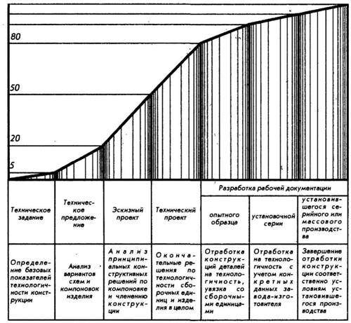
Rice. 148
Let us now get acquainted with the technological requirements for both individual parts and the mechanism, the machine as a whole.
The accumulated experience in the field of mechanical engineering technology has made it possible to outline specific examples of design solutions that can be considered as recommendations that deserve attention when designing parts, assembly units, machines and mechanisms.
Constructors are mostly people with imaginative thinking and good visual memory. For them, drawings and sketches say much more than many pages of explanations. Therefore, almost every statement below is accompanied by constructive examples.
Elements of furniture products have sections of a very different profile, furniture parts can also be connected in different ways - flush, with an overhang, with a plate, etc. Let's get acquainted with some concepts related to the design and shape of furniture products.
Layouts are blanks that cover the edges of shields and frames. In cross section, they can be rectangular and shaped, installed flush with the shield, with a ledge or ledge.
Bead - a bar used to fasten glass or panels inserted into a quarter.
Rice. 61. Elements of a furniture product: 1 - bar; 2 - layout; 3 - glazing bead; 4 - panel; 5 - chamfer; 6 - softening; 7 - rounding; 8 - fillet; 9 - kalevka; 10 - fold; 11 - the size of the plate; 12 - overhang size
Panels - shields nested inside the frame. There are flat, with beveled or profiled edges, the so-called figurines.
A chamfer is a cut edge of the edge of a part, softening is a slight rounding of a sharp edge of an edge (radius 1-2 mm), and a more significant rounding is called a chamfer. Chamfering, softening and heaving serve to protect the rib from damage (soften the sharpness of the edge and thereby increase the resistance of the material to external loads).
A fillet is a semicircular recess on the rib or a part of a part, a kalevka is a figuratively processed edge of an element for the purpose of decorative design of the product.
Falz - a rectangular recess. The protruding part obtained during the selection of the fold is called a sponge. A fold with equal sides is called a quarter.
Platik - a ledge measuring 2-6 mm. The purpose of the plate is to hide the gap, mismatches in the same plane of the connected elements and other defects. Plates simplify the assembly of the product and, as a rule, are provided for by the design.
Overhang - a part of the stool seat, table top, etc., protruding beyond the base. Its size is structurally taken to be 10-50 mm.
Wood products are formed from parts and assembly units. Details are made from the source material without assembly, they can be in the form of a bar, shield, frame. Assembly units may also have such forms, but they are obtained by assembling individual parts. In other words: the main structural elements of wood products can be in the form of parts and assembly units, which in turn can be in the form of bars, shields, frames, etc.
A bar is the simplest structural element of a product, it can be of different shapes and designs. It is believed that the width of the bar should be no more than twice its thickness.
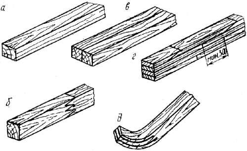
Rice. 62. Types of bars: a - solid, b - glued along the length, c - glued along the width, d - glued along the thickness and length, e - bent-propylene
must be taken into account when designing a product. that bars made from a single piece of wood are more prone to cracking and warping than glued ones. In this regard, there are size restrictions: in cross section - 100 × 50 mm, in length - 2000 mm. Details large sizes make glued, as they are more durable and dimensionally stable. Even small bars in cross section and length are recommended to be made composite.
When gluing workpieces in width and thickness, joints are used along the face and edge. In terms of thickness and length, the simplest partial gluing of workpieces can be carried out end-to-end. The distance between such connections in adjacent plots should be at least 300 mm. You can also glue on a mustache or toothed spikes 5 mm long with the joints arranged apart.
When gluing blanks along the length, a toothed spike is used. For lightly loaded parts, toothed spikes have a length of 10-20 mm, for parts operating in stressed structures - 32-50 mm. The dimensions of the sections of parts are assigned taking into account standard sizes blanks and allowances for processing.
In the longitudinal direction, the bars can be rectangular and curvilinear in shape, rectangular and shaped in cross section, and, depending on the manufacturing method, they can be sawn, pressed, bent, bent-glued, bent-propylene. Sawn and bent bars are made from solid wood. The design of bent bars depends on the purpose. Pressed and bent-glued bars are made from wood plates, plywood, veneer. The directions of the fibers in bent-glued veneer bars can be mutually perpendicular or longitudinal in all layers (in the latter case, the rigidity of the bars is higher). Such bars are used for the manufacture of legs of chairs, armchairs, tables, etc. Bent-propylene bars are a kind of bent-glued ones. Longitudinal cuts are preliminarily made in them, into which structural elements are inserted on glue (usually from peeled veneer). The sawn part of the bar with nested elements is bent and glued. After gluing, the workpiece retains its shape. Such bars are used if it is necessary to have parts with curvature of only one end.
Bars are the simplest starting element in the design of products. By gluing and assembling from bars, you can get a variety of structural elements - shields, frames, boxes, product frames.
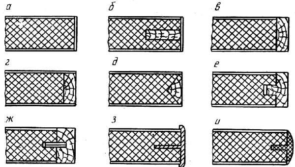
Frames also vary in design and shape. They are made from bars connected to each other by angular and middle ties or staples, as well as from plate materials (by milling).
When constructing bar frames with lined edges, the joints should be used so that the ends of the spikes do not go out onto the lined surface. This is done because over time the spikes will become noticeable. True, the manufacture of frames with spiked joints of bars is laborious, therefore, if the frame does not take much effort, the parts can also be connected with brackets. Such a connection is intermediate, its strength must ensure the performance of a technological operation (for example, gluing in a press).

Rice. 63. Various frame and box designs: a - bar frame; b - shield frame, c - box
Panel frames can be made of coated particle boards, in which case the frame clearance is performed by milling. At furniture factories, such frames are made whole-pressed from shredded wood, lumpy waste of particle boards or blockboards by pre-assembly and subsequent cladding.
The opening of the frame is closed with glass or a panel made of plywood or chipboard (usually lined). Panels and glass are inserted into a quarter or fastened on both sides with glazing beads. Panels can be inserted into the groove, then they cannot be removed from the frame.
Boxes are a kind of frames (wide plates of bars are located perpendicular to the plane of the box itself). Boxes are widely used in furniture products to form the body and in the manufacture of boxes. Depending on the purpose, the boxes may have different connections. The details of the boxes are made of wood, various plates, plastics, metal.
One of the main shaping structural elements of wood products are shields. They are made from various materials and have different designs. The most common boards are made of chipboard, lined with various materials (veneer, films).
Boards are also used in the form of frames with different fillings. They are glued from massive plots to a smooth fugue, to a groove and a crest, to a rail. To reduce the warping of such shields, various tips are used, tying with frames, and the plots are made of small width.
Non-standard blockboards are obtained by gluing the base of wood shields with peeled veneer. If a base of laths not glued together is used, the thickness of the cladding layers must be at least 3 mm, and for boards with glued laths - at least 1.5 mm.

Rice. 64. Shield designs: a - three-layer carpentry; b - frame with continuous filling; c - hollow with slatted wood filling; d, e - hollow with slatted plywood or fiberboard filling; e - hollow with honeycomb filling from resin-impregnated paper
Shields with solid filling are made in the form of a frame filled with a chip-and-glue mixture, foam or other material.
Hollow boards are also used, which are a frame pasted over with veneer, plywood or fiberboard. To ensure rigidity, a rack or honeycomb core is placed between the linings. Such boards are lighter, strong enough, have low sound and thermal conductivity, but are subject to greater warpage than chipboard boards, have lower rigidity in a plane perpendicular to the face, as well as surface waviness due to retraction of the facings into the gaps between the laths.
Fillers of hollow panels can be waste plywood, fibreboard, joinery and chipboard. The frames of such panels can also be made from chipboard waste, as for furniture they can be 35-50 mm wide. In order for the retraction of the facings to be small, the fillers are placed perpendicular to the direction of the lining fibers, and the distance between the filler rails should be no more than 20b (b is the thickness of the facing layer). In hollow panels with honeycomb filling, the width of the cells should not exceed 20 mm when facing with two layers of veneer, 30 mm - with plywood 3-4 mm thick with simultaneous facing with sliced veneer. Such boards are little subject to retraction of facings and can be used in the manufacture of furniture.
Hollow shields can be one-sided, i.e., asymmetrical design. They are installed tightly in the product, otherwise they will warp.
The edges of panel parts are structurally designed depending on the type and purpose of the panels. In most cases, the edges of particle boards are faced with sliced veneer or edge plastic. On the end edges of the joiner's plates, linings connected in a groove and a comb should be glued. Ledge edges with cores made of glued laths can be veneered without prior gluing of facings.
Rice. 65. Finishing the edges of panel parts: a, b - facing with sliced veneer or edge plastic; c–e – by gluing solid wood facings onto a smooth fugue; e - the same, in a tongue and groove; g - the same, on a plug-in rail; h, and - metal or plastic layouts
If the ends of the spikes and bars do not protrude onto the outer surface, the edges of hollow and other frame shields can be faced without facings. The edges of all types of shields can be closed with profiled metal or plastic facings. Often the edges of panel parts are made not only straight, but also profiled. This is how the edges of parts made of particle boards are also designed. To do this, they are pre-profiled, and if necessary, polished and lined with special edging material.
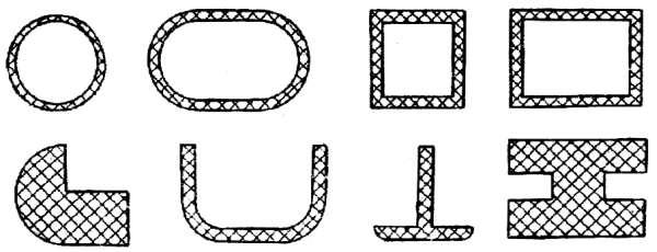
The optimal design requires that the loaded sections of the parts have sections larger area or increased strength. For example, shelves working in bending must have high rigidity of the facing layers. For parts of this type, it is advisable to use plates with oriented chips, as well as profiled sections (in the figure, positions a and b).

Rice. 66. Sections of panel elements and furniture doors
Furniture doors can have sections shown in fig. 66 (positions c–e).
For rigidity and the possibility of fastening fittings around the perimeter, the door must have a thickened belt or side, while the middle part can be in the form of a panel. Thin slabs, plywood, fiberboard, glass, sheet polystyrene, sheet glass lined with sliced veneer can be used as panels. These elements, with their relatively small thickness, have high bending strength.
It is possible to make a furniture door from a chipboard of small thickness (12 mm, in the figure, position a). On the inner side of the door, strips of solid fibreboard 3-4 mm thick are glued along the length, which makes it possible to fasten doors using conventional fittings. The door structure shown in Fig. (b), consists of slabs of two thicknesses: its outermost elements are made of a 19 mm thick slab, and the middle one, acting as a panel, is 10 mm. Position "b" shows a frame-paneled door with a frame made of 14 mm thick board and a 2.5 mm thick fiberboard panel.

Rice. 67. Door structures made of slabs of different thicknesses
For a variety of designs in one product, you can use chipboards of different thicknesses, for example, for lightly loaded elements - 8-10 mm thick, as the main structural material - 15-16 mm, and for heavily loaded parts - more than 16 mm.
Instead of solid wood and particle boards, medium-density fibreboards (dry-processed) with a thickness of 8-35 mm can also be used.
Rice. 68. Sections of profile molded elements
Molded elements made of wood-glue pulp or veneer can be used to make table legs, armchairs, bases for soft elements, decorative elements, etc.