LED driver for powering the receiver. TEXAS INSTRUMENTS LED Driver Review. Functions of transistors on the diagram
An integral part of any high-quality LED lamp or luminaire is the driver. In relation to lighting, the concept of “driver” should be understood as an electronic circuit that converts the input voltage into a stabilized current of a given value. The functionality of the driver is determined by the width of the input voltage range, the ability to adjust output parameters, susceptibility to changes in the supply network and efficiency.
The quality indicators of the lamp or lamp as a whole, service life and cost depend on the listed functions. All power supplies (PS) for LEDs are conventionally divided into linear and pulse type. Linear power supplies can have a current or voltage stabilization unit. Radio amateurs often construct circuits of this type with their own hands using the LM317 microcircuit. Such a device is easy to assemble and has low cost. But, due to the very low efficiency and obvious limitations on the power of connected LEDs, the prospects for the development of linear converters are limited.
Switching drivers can have an efficiency of more than 90% and a high degree of protection against network interference. Their power consumption is tens of times less than the power supplied to the load. Thanks to this, they can be manufactured in a sealed case and are not afraid of overheating.
The first pulse stabilizers had a complex device without idle protection. Then they were modernized and, due to the rapid development of LED technologies, specialized chips with frequency and pulse width modulation appeared.
LED power supply circuit based on a capacitor divider
Unfortunately, the design of cheap 220V LED lamps from China does not provide either a linear or a pulse stabilizer. Motivated by the exceptionally low price of the finished product, the Chinese industry was able to simplify the power supply circuit as much as possible. It is not correct to call it a driver, since there is no stabilization here. The figure shows that the electrical circuit of the lamp is designed to operate from a 220V network. The alternating voltage is reduced by the RC circuit and supplied to the diode bridge. Then the rectified voltage is partially smoothed by a capacitor and is supplied to the LEDs through a current-limiting resistor. This circuit does not have galvanic isolation, that is, all elements are constantly at high potential.
As a result, frequent sags in the mains voltage lead to flickering of the LED lamp. Conversely, an excessive network voltage causes an irreversible aging process of the capacitor with loss of capacity, and, sometimes, causes its rupture. It is worth noting that another serious negative side of this scheme is the accelerated process of LED degradation due to unstable supply current.
Driver circuit for CPC9909
 Modern pulse drivers for LED lamps have a simple circuit, so you can easily make it even with your own hands. Today, to build drivers, a number of integrated circuits are produced, specifically designed to control high-power LEDs. To simplify the task for lovers of electronic circuits, developers of integrated drivers for LEDs provide typical connection diagrams and calculations of wiring components in the documentation.
General information
The American company Ixys has launched the production of the CPC9909 chip, designed to control LED assemblies and high-brightness LEDs. The driver based on CPC9909 is small in size and does not require large investments. The CPC9909 IC is manufactured in a planar design with 8 pins (SOIC-8) and has a built-in voltage regulator.
Thanks to the presence of a stabilizer, the operating range of the input voltage is 12-550V from a DC source. The minimum voltage drop across LEDs is 10% of the supply voltage. Therefore, the CPC9909 is ideal for connecting high voltage LEDs. The IC works perfectly in the temperature range from -55 to +85°C, which means it is suitable for designing LED lamps and luminaires for outdoor lighting.
Pin assignment
It is worth noting that with the help of CPC9909 you can not only turn on and off a powerful LED, but also control its glow. To learn about all the capabilities of the IC, consider the purpose of its conclusions. 
- VIN. Designed to supply power voltage.
- CS. Designed to connect an external current sensor (resistor), with which the maximum LED current is set.
- GND. General driver output.
- GATE. Output of the microcircuit. Supplies a modulated signal to the gate of the power transistor.
- P.W.M.D. Low frequency dimming input.
- VDD. Output for supply voltage regulation. In most cases, it is connected via a capacitor to a common wire.
- L.D. Designed to set analog dimming.
- RT. Designed to connect a time setting resistor.
Scheme and its principle of operation
A typical connection of the CPC9909 powered from a 220V network is shown in the figure. The circuit is capable of driving one or more high-power or High Brightness LEDs. The circuit can be easily assembled with your own hands, even at home. The finished driver does not require adjustment, taking into account the correct selection of external elements and compliance with the rules for their installation.  The driver for a 220V LED lamp based on CPC9909 works using the pulse frequency modulation method. This means that the pause time is a constant value (time-off=const). The alternating voltage is rectified by a diode bridge and smoothed by a capacitive filter C1, C2. Then it goes to the VIN input of the microcircuit and starts the process of generating current pulses at the GATE output. The IC's output current drives power transistor Q1. At the moment the transistor is open (pulse time “time-on”), the load current flows through the circuit: “+ diode bridge” – LED – L – Q1 – R S – “-diode bridge”.
  During this time, the inductor accumulates energy in order to transfer it to the load during a pause. When the transistor closes, the inductor energy provides load current in the circuit: L – D1 – LED – L.
  The process is cyclical, resulting in a sawtooth current through the LED. The maximum and minimum value of the saw depends on the inductance of the inductor and the operating frequency.
  The pulse frequency is determined by the value of the resistance RT. The amplitude of the pulses depends on the resistance of the resistor RS. The LED current is stabilized by comparing the internal reference voltage IC with voltage drop across R S . A fuse and a thermistor protect the circuit from possible emergency conditions.
Calculation of external elements
Frequency setting resistor
The duration of the pause is set by an external resistor R T and determined using a simplified formula:
t pause =R T /66000+0.8 (µs).
In turn, the pause time is related to the duty cycle and frequency:
t pause =(1-D)/f (s), where D is the duty cycle, which is the ratio of the pulse time to the period.
Current sensor
The resistance rating R S specifies the amplitude value of the current through the LED and is calculated by the formula: R S =U CS /(I LED +0.5*I L pulse), where U CS is the calibrated reference voltage equal to 0.25V;
I LED – current through the LED;
I L pulse – the value of load current ripple, which should not exceed 30%, that is, 0.3*I LED.
After the transformation, the formula will take the form: R S =0.25/1.15*I LED (Ohm).
The power dissipated by the current sensor is determined by the formula: P S =R S *I LED *D (W).
A resistor with a power reserve of 1.5-2 times is accepted for installation.
Throttle
As is known, the inductor current cannot change abruptly, increasing during the pulse and decreasing during the pause. The radio amateur's task is to select a coil with an inductance that provides a compromise between the quality of the output signal and its dimensions. To do this, remember the ripple level, which should not exceed 30%. Then you will need an inductance with a nominal value:
L=(US LED *t pause)/ I L pulse, where U LED is the voltage drop across the LED(s), taken from the I-V characteristic curve.
Power filter
Two capacitors are installed in the power circuit: C1 – to smooth out the rectified voltage and C2 – to compensate for frequency interference. Since the CPC9909 operates over a wide input voltage range, there is no need for a large electrolytic C1 capacitance. 22 uF will be enough, but more is possible. The capacitance of metal film C2 for a circuit of this type is standard - 0.1 μF. Both capacitors must withstand a voltage of at least 400V.
However, the chip manufacturer insists on installing capacitors C1 and C2 with low equivalent series resistance (ESR) to avoid the negative impact of high-frequency noise that occurs when the driver switches.
Rectifier
The diode bridge is selected based on the maximum forward current and reverse voltage. For operation in a 220V network, its reverse voltage must be at least 600V. The calculated value of the forward current directly depends on the load current and is defined as: I AC =(π*I LED)/2√2, A.
The resulting value must be multiplied by two to increase the reliability of the circuit.
Selecting remaining circuit elements
Capacitor C3 installed in the power supply circuit of the microcircuit should have a capacity of 0.1 µF with a low ESR value, similar to C1 and C2. The unused pins PWMD and LD are also connected to the common wire via C3.
Transistor Q1 and diode D1 operate in pulse mode. Therefore, the choice should be made taking into account their frequency properties. Only elements with a short recovery time will be able to contain the negative impact of transients at the moment of switching at a frequency of about 100 kHz. The maximum current through Q1 and D1 is equal to the amplitude value of the LED current, taking into account the selected duty cycle: I Q1 = I D1 = D*I LED, A.
The voltage applied to Q1 and D1 is pulsed in nature, but no more than the rectified voltage taking into account the capacitive filter, that is, 280V. The choice of power elements Q1 and D1 should be made with a margin, multiplying the calculated data by two.
The fuse protects the circuit from emergency short circuits and must withstand the maximum load current for a long time, including impulse noise.
I FUSE =5*I AC , A.
Installing an RTH thermistor is necessary to limit the driver inrush current when the filter capacitor is discharged. With its resistance, RTH must protect the diodes of the bridge rectifier from breakdown in the initial seconds of operation.
R TH =(√2*220)/5*I AC, Ohm.
Other options for enabling the CPC9909
Soft start and analogue dimming
If desired, the CPC9909 can provide a soft turn on of the LED as its brightness gradually increases. Soft start is realized using two fixed resistors connected to the LD pin, as shown in the figure. This solution allows you to extend the life of the LED.
Also, the LD pin allows you to implement the analog dimming function. To do this, the 2.2 kOhm resistor is replaced with a variable resistor 5.1 kOhm, thereby smoothly changing the potential at the LD pin.
Pulse dimming
You can control the glow of the LED by sending pulses rectangular shape to the PWMD (pulse width modulation dimming) output. To do this, a microcontroller or a pulse generator is used with mandatory separation through an optocoupler.
In addition to the considered driver option for LED lamps, there are similar circuit solutions from other manufacturers: HV9910, HV9961, PT4115, NE555, RCD-24, etc. Each of them has its own strengths and weak spots, but in general, they successfully cope with the imposed load when assembling them with their own hands.
Read also
must be connected to the power supply through special devices that stabilize the current - drivers for LEDs. These are 220V AC voltage converters D.C. with the parameters necessary for the operation of light diodes. Only with their presence can one guarantee stable operation, long service life of LED sources, declared brightness, protection against short circuits and overheating. The choice of drivers is small, so it is better to first purchase a converter and then select it for it. You can assemble the device yourself using a simple diagram. Read about what an LED driver is, which one to buy and how to use it correctly in our review.
- These are semiconductor elements. The brightness of their glow is determined by current, not voltage. For them to work, they need a stable current of a certain value. At a p-n junction, the voltage drops by the same number of volts for each element. Provide optimal performance LED sources taking into account these parameters is the task of the driver.
Exactly what power is needed and how much it drops at the p-n junction should be indicated in the passport data of the LED device. The converter parameter range must fit within these values.

Essentially, a driver is a . But the main output parameter of this device is stabilized current. They are produced according to the principle of PWM conversion using special microcircuits or based on transistors. The latter are called simple.
The converter is powered from a regular network and outputs a voltage of a given range, which is indicated in the form of two numbers: the minimum and maximum values. Usually from 3 V to several tens. For example, using a converter with an output voltage of 9÷21 V and a power of 780 mA, it is possible to provide operation of 3÷6, each of which creates a drop in the network of 3 V.
Thus, a driver is a device that converts current from a 220 V network to the specified parameters of the lighting device, ensuring its normal operation and long term operation.

Where is it used?
The demand for converters is growing along with the popularity of LEDs. - These are economical, powerful and compact devices. They are used for a variety of purposes:
- for lanterns;
- at home;
- for arrangement;
- in car and bicycle headlights;
- in small lanterns;
When connecting to a 220 V network, you always need a driver; if you use constant voltage, you can get by with a resistor.

How the device works
The principle of operation of LED drivers for LEDs is to maintain a given output current, regardless of voltage changes. The current passing through the resistances inside the device is stabilized and acquires the desired frequency. Then it passes through a rectifying diode bridge. At the output we get a stable forward current, sufficient to operate a certain number of LEDs.
Main characteristics of drivers
Key parameters of current conversion devices that you need to rely on when choosing:
- Rated power of the device. It is indicated in the range. Maximum value there must be a little more than the power consumption of the connected lighting fixture.
- Output voltage. The value must be greater than or equal to the total voltage drop across each circuit element.
- Rated current. Must match the power of the device to provide sufficient brightness.
Depending on these characteristics, it is determined which LED sources can be connected using a specific driver.

Types of current converters by device type
Drivers are produced in two types: linear and pulse. They have the same function, but the scope of application, technical features and cost differ. A comparison of converters of different types is presented in the table:
| Device type | Specifications | pros | Minuses | Scope of application |
| Current generator on a transistor with a p-channel, smoothly stabilizes the current at alternating voltage | No interference, inexpensive | Efficiency less than 80%, gets very hot | Low-power LED lamps, strips, flashlights |
| Operates on the basis of pulse width modulation | High efficiency (up to 95%), suitable for powerful devices, extends the service life of elements | Creates electromagnetic interference | Car tuning, street lighting, household LED sources |


How to choose a driver for LEDs and calculate its technical parameters
A driver for an LED strip will not be suitable for a powerful street lamp and vice versa, so it is necessary to calculate the main parameters of the device as accurately as possible and take into account the operating conditions.
| Parameter | What does it depend on | How to calculate |
| Device power calculation | Determined by the power of all connected LEDs | Calculated using the formula P = PLED source × n , Where P – is the driver power; PLED source – power of one connected element; n - amount of elements. For a power reserve of 30% you need to multiply P by 1.3. The resulting value is the maximum driver power required to connect the lighting fixture |
| Output voltage calculation | Determined by the voltage drop across each element | The value depends on the glow color of the elements; it is indicated on the device itself or on the packaging. For example, you can connect 9 green or 16 red LEDs to a 12V driver. |
| Current calculation | Depends on the power and brightness of the LEDs | Determined by the parameters of the connected device |
Converters are available with or without housing. The former look more aesthetically pleasing and are protected from moisture and dust, the latter are used for hidden installation and are cheaper. Another characteristic that must be taken into account is the permissible operating temperature. It is different for linear and pulse converters.
Important! The packaging with the device must indicate its main parameters and manufacturer.

Methods for connecting current converters
LEDs can be connected to the device in two ways: in parallel (several chains with the same number of elements) and in series (one by one in one chain).
To connect 6 elements with a voltage drop of 2 V in parallel in two lines, you will need a 6 V 600 mA driver. And when connected in series, the converter must be designed for 12 V and 300 mA.
A serial connection is better because all the LEDs will glow equally, whereas with a parallel connection the brightness of the lines may vary. When connecting a large number of elements in series, a driver with a high output voltage will be required.

Dimmable current converters for LEDs
- This is the regulation of the intensity of light emanating from a lighting fixture. Dimmable drivers allow you to change the input and output current parameters. Due to this, the brightness of the LEDs increases or decreases. When using regulation, it is possible to change the color of the glow. If the power is less, then the white elements may turn yellow, if more, then blue.
Chinese drivers: is it worth saving?
Drivers are produced in China in huge quantities. They are low cost, so they are quite in demand. They have galvanic isolation. Their technical parameters are often overestimated, so it’s worth taking this into account when buying a cheap device.
Most often these are pulse converters, with a power of 350÷700 mA. They do not always have a housing, which is even convenient if the device is purchased for the purpose of experimentation or training.
Disadvantages of Chinese products:
- simple and cheap microcircuits are used as the basis;
- devices do not have protection against power fluctuations and overheating;
- create radio interference;
- create high-level ripple at the output;
- They do not last long and are not guaranteed.
Not all Chinese drivers are bad; more reliable devices are also produced, for example, based on PT4115. They can be used to connect household LED sources, flashlights, and strips.
Driver lifespan
The service life of an ice driver for LED lamps depends on external conditions and the original quality of the device. The estimated service life of the driver is from 20 to 100 thousand hours.
The following factors can affect the service life:
- temperature changes;
- high humidity;
- power surges;
- incomplete load of the device (if the driver is designed for 100 W, but uses 50 W, the voltage returns back, which causes an overload).
Well-known manufacturers provide a warranty on drivers for an average of 30 thousand hours. But if the device was used incorrectly, the buyer is responsible. If the LED source does not turn on, or perhaps the problem is in the converter, incorrect connection, or malfunction of the lighting fixture itself.
How to check the LED driver for functionality, see the video below:
DIY driver circuit for LEDs with a brightness controller based on RT4115
A simple current converter can be assembled based on a ready-made Chinese PT4115 microcircuit. It is reliable enough for use. Chip characteristics:
- Efficiency up to 97%;
- there is an output for a device that regulates brightness;
- protected from load breaks;
- maximum stabilization deviation 5%;
- input voltage 6÷30 V;
- output power 1.2 A.
The chip is suitable for powering an LED source over 1 W. Has a minimum of strapping components.
Decoding the outputs of the microcircuit:
- S.W.– output switch;
- DIM– dimming;
- GND– signal and power element;
- CIN– capacitor
- CSN– current sensor;
- VIN- supply voltage.
Even a novice master can assemble a driver based on this chip.

220V LED lamp driver circuit
In the case of the current stabilizer, it is installed in the base of the device. And it is based on inexpensive microcircuits, for example, CPC9909. Such lamps must be equipped with a cooling system. They last much longer than any other, but it is better to give preference to trusted manufacturers, since the Chinese ones have noticeable hand soldering, asymmetry, lack of thermal paste and other shortcomings that reduce service life.

How to make a driver for LEDs with your own hands
The device can be made from any unnecessary phone charger. It is necessary to make only minimal improvements and the microcircuit can be connected to LEDs. It is enough to power 3 1 W elements. To connect a more powerful source, you can use boards from fluorescent lamps.
Important! During work it is necessary to observe safety precautions. Touching exposed parts may result in an electric shock of up to 400 V.
| Photo | Stage of assembling the driver from the charger |
 | Remove the housing from the charger. |
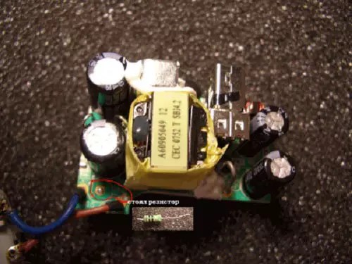 | Using a soldering iron, remove the resistor that limits the voltage supplied to the phone. |
 | Install a tuning resistor in its place until it needs to be set to 5 kOhm. |
 | Using a serial connection, solder the LEDs to the output channel of the device. |
 | Remove the input channels with a soldering iron, and in their place solder a power cord to connect to a 220 V network. |
 | Check the operation of the circuit, set the regulator on the trimming resistor to the required voltage so that the LEDs shine brightly but do not change color. |
 Example of a driver circuit for LEDs from a 220 V network
 Drivers for LEDs: where to buy and how much they cost
You can purchase stabilizers for LED lamps and microcircuits for them in radio components stores, electrical equipment stores, and on many online trading platforms. The last option is the most economical. The cost of the device depends on its technical characteristics, type and manufacturer. Average prices for some types of drivers are shown in the table below.
The widespread use of LEDs has led to the mass production of power supplies for them. Such blocks are called drivers. Their main feature is that they are able to stably maintain a given current at the output. In other words, a driver for light emitting diodes (LEDs) is a source of current to power them.
Purpose
Since LEDs are semiconductor elements, the key characteristic that determines the brightness of their glow is not voltage, but current. In order for them to be guaranteed to work for the stated number of hours, a driver is needed - it stabilizes the current flowing through the LED circuit. It is possible to use low-power light-emitting diodes without a driver; in this case, its role is played by a resistor.
Application
Drivers are used both when powering the LED from a 220V network, and from DC voltage sources of 9-36 V. The former are used when lighting rooms with LED lamps and strips, the latter are more often found in cars, bicycle headlights, portable lanterns, etc.
Principle of operation
As already mentioned, the driver is a current source. Its differences from a voltage source are illustrated below.
The voltage source produces a certain voltage at its output, ideally independent of the load.
For example, if you connect a 40 Ohm resistor to a 12 V source, a current of 300 mA will flow through it.
If you connect two resistors in parallel, the total current will be 600 mA at the same voltage.

The driver maintains the specified current at its output. The voltage may change in this case.
Let's also connect a 40 Ohm resistor to the 300 mA driver.

The driver will create a 12V voltage drop across the resistor.
If you connect two resistors in parallel, the current will still be 300 mA, but the voltage will drop to 6 V:

Thus, an ideal driver is capable of delivering the rated current to the load regardless of voltage drop. That is, an LED with a voltage drop of 2 V and a current of 300 mA will burn as brightly as an LED with a voltage of 3 V and a current of 300 mA.
Main characteristics
When selecting, you need to take into account three main parameters: output voltage, current and power consumed by the load.
The driver output voltage depends on several factors:
- LED voltage drop;
- number of LEDs;
- connection method.
The driver output current is determined by the characteristics of the LEDs and depends on the following parameters:
- LED power;
- brightness.
The power of LEDs affects the current they consume, which can vary depending on the required brightness. The driver must provide them with this current.
Load power depends on:
- power of each LED;
- their quantities;
- colors.
In general, power consumption can be calculated as

where Pled is the LED power,
N is the number of connected LEDs.
The maximum driver power should not be less.
It is worth considering that for stable operation of the driver and to prevent its failure, a power reserve of at least 20-30% should be provided. That is, the following relationship must be satisfied:

where Pmax is the maximum driver power.
In addition to the power and number of LEDs, the load power also depends on their color. LEDs of different colors have different voltage drops for the same current. For example, the red XP-E LED has a voltage drop of 1.9-2.4 V at 350 mA. Its average power consumption is thus about 750 mW.
The green XP-E has a drop of 3.3-3.9 V at the same current, and its average power will be about 1.25 W. That is, a driver rated at 10 watts can power either 12-13 red LEDs or 7-8 green ones.
How to choose a driver for LEDs. LED connection methods
Let's say there are 6 LEDs with a voltage drop of 2 V and a current of 300 mA. You can connect them in various ways, and in each case you will need a driver with certain parameters:

It is unacceptable to connect 3 or more LEDs in parallel in this way, since too much current may flow through them, as a result of which they will quickly fail.
Please note that in all cases the driver power is 3.6 W and does not depend on the method of connecting the load.
Thus, it is more advisable to select a driver for LEDs already at the stage of purchasing the latter, having previously determined the connection diagram. If you first purchase the LEDs themselves, and then select a driver for them, this may not be an easy task, since the likelihood that you will find exactly the power source that can ensure the operation of exactly this number of LEDs connected according to a specific circuit is small.
Kinds
In general, LED drivers can be divided into two categories: linear and switching.
The linear output is a current generator. It provides stabilization of the output current with an unstable input voltage; Moreover, the adjustment occurs smoothly, without creating high-frequency electromagnetic interference. They are simple and cheap, but their low efficiency (less than 80%) limits their scope of application to low-power LEDs and strips.

Pulse devices are devices that create a series of high-frequency current pulses at the output.

They usually operate on the principle of pulse width modulation (PWM), that is, the average value of the output current is determined by the ratio of the pulse width to their repetition period (this value is called the duty cycle).
![]()
The diagram above shows the operating principle of a PWM driver: the pulse frequency remains constant, but the duty cycle varies from 10% to 80%. This leads to a change in the average value of the output current I cp.
Such drivers are widely used due to their compactness and high efficiency (about 95%). The main disadvantage is the higher level of electromagnetic interference compared to linear ones.
220V LED driver
For inclusion in a 220 V network, both linear and pulsed ones are produced. There are drivers with and without galvanic isolation from the network. The main advantages of the former are high efficiency, reliability and safety.
Without galvanic isolation are usually cheaper, but less reliable and require care when connecting, as there is a risk of electric shock.
Chinese drivers
The demand for drivers for LEDs contributes to their mass production in China. These devices are pulsed current sources, usually 350-700 mA, often without a housing.

Chinese driver for 3w LED
Their main advantages are low price and the presence of galvanic isolation. The disadvantages are the following:
- low reliability due to the use of cheap circuit solutions;
- lack of protection against overheating and fluctuations in the network;
- high level of radio interference;
- high level of output ripple;
- fragility.
Life time
Typically, the service life of the driver is shorter than that of the optical part - manufacturers provide a guarantee of 30,000 hours of operation. This is due to factors such as:
- instability of mains voltage;
- temperature changes;
- humidity level;
- driver load.
The weakest link of the LED driver is the smoothing capacitors, which tend to evaporate the electrolyte, especially in conditions of high humidity and unstable supply voltage. As a result, the level of ripple at the driver output increases, which negatively affects the operation of the LEDs.
Also, the service life is affected by incomplete driver load. That is, if it is designed for 150 W, but operates at a load of 70 W, half of its power returns to the network, causing it to overload. This causes frequent power failures. We recommend reading about.
Driver circuits (chips) for LEDs
Many manufacturers produce specialized driver chips. Let's look at some of them.
ON Semiconductor UC3845 is a pulse driver with an output current of up to 1A. The driver circuit for a 10w LED on this chip is shown below.

Supertex HV9910 is a very common pulse driver chip. The output current does not exceed 10 mA and has no galvanic isolation.
A simple current driver on this chip is shown below.

Texas Instruments UCC28810. Network pulse driver has the ability to organize galvanic isolation. Output current up to 750 mA.

Another microcircuit from this company, a driver for powering powerful LM3404HV LEDs, is described in this video:
The device operates on the principle of a Buck Converter type resonant converter, that is, the function of maintaining the required current here is partially assigned to a resonant circuit in the form of coil L1 and Schottky diode D1 (a typical circuit is shown below). It is also possible to set the switching frequency by selecting a resistor R ON.

Maxim MAX16800 is a linear microcircuit that operates at low voltages, so you can build a 12 volt driver on it. The output current is up to 350 mA, so it can be used as a power driver for a powerful LED, flashlight, etc. There is a possibility of dimming. A typical diagram and structure is presented below.

Conclusion
LEDs are much more demanding on the power supply than other light sources. For example, exceeding the current by 20% for a fluorescent lamp will not entail a serious deterioration in performance, but for LEDs the service life will be reduced several times. Therefore, you should choose a driver for LEDs especially carefully.
The standard RT4115 LED driver circuit is shown in the figure below: 
The supply voltage should be at least 1.5-2 volts higher than the total voltage across the LEDs. Accordingly, in the supply voltage range from 6 to 30 volts, from 1 to 7-8 LEDs can be connected to the driver.
Maximum supply voltage of the microcircuit 45 V, but operation in this mode is not guaranteed (better pay attention to a similar microcircuit).
The current through the LEDs has a triangular shape with a maximum deviation from the average value of ±15%. The average current through the LEDs is set by a resistor and calculated by the formula:
I LED = 0.1 / R
The minimum permissible value is R = 0.082 Ohm, which corresponds to a maximum current of 1.2 A.
The deviation of the current through the LED from the calculated one does not exceed 5%, provided that resistor R is installed with a maximum deviation from the nominal value of 1%.
So, to turn on the LED at constant brightness, we leave the DIM pin hanging in the air (it is pulled up to the 5V level inside the PT4115). In this case, the output current is determined solely by resistance R.
If we connect a capacitor between the DIM pin and ground, we get the effect of smooth lighting of the LEDs. The time it takes to reach maximum brightness will depend on the capacitor capacity; the larger it is, the longer the lamp will light up.
For reference: Each nanofarad of capacitance increases the turn-on time by 0.8 ms. 
If you want to make a dimmable driver for LEDs with brightness adjustment from 0 to 100%, then you can resort to one of two methods:
- First way assumes that a constant voltage in the range from 0 to 6V is supplied to the DIM input. In this case, brightness adjustment from 0 to 100% is carried out at a voltage at the DIM pin from 0.5 to 2.5 volts. Increasing the voltage above 2.5 V (and up to 6 V) does not affect the current through the LEDs (the brightness does not change). On the contrary, reducing the voltage to a level of 0.3V or lower leads to the circuit turning off and putting it into standby mode (the current consumption drops to 95 μA). Thus, you can effectively control the operation of the driver without removing the supply voltage.
- Second way involves supplying a signal from a pulse-width converter with an output frequency of 100-20000 Hz, the brightness will be determined by the duty cycle (pulse duty cycle). For example, if the high level lasts 1/4 of the period, and the low level, respectively, 3/4, then this will correspond to a brightness level of 25% of the maximum. You must understand that the driver operating frequency is determined by the inductance of the inductor and in no way depends on the dimming frequency.
The PT4115 LED driver circuit with constant voltage dimmer is shown in the figure below: 
This circuit for adjusting the brightness of the LEDs works great due to the fact that inside the chip the DIM pin is “pulled up” to the 5V bus through a 200 kOhm resistor. Therefore, when the potentiometer slider is in its lowest position, a voltage divider of 200 + 200 kOhm is formed and a potential of 5/2 = 2.5V is formed at the DIM pin, which corresponds to 100% brightness.
How the scheme works
At the first moment of time, when the input voltage is applied, the current through R and L is zero and the output switch built into the microcircuit is open. The current through the LEDs begins to gradually increase. The rate of current rise depends on the magnitude of the inductance and supply voltage. The in-circuit comparator compares the potentials before and after resistor R and, as soon as the difference is 115 mV, a low level appears at its output, which closes the output switch.
Thanks to the energy stored in the inductance, the current through the LEDs does not disappear instantly, but begins to gradually decrease. The voltage drop across the resistor R gradually decreases. As soon as it reaches a value of 85 mV, the comparator will again issue a signal to open the output switch. And the whole cycle repeats all over again.
If it is necessary to reduce the range of current ripples through the LEDs, it is possible to connect a capacitor in parallel with the LEDs. The larger its capacity, the more the triangular shape of the current through the LEDs will be smoothed out and the more similar it will become to a sinusoidal one. The capacitor does not affect the operating frequency or efficiency of the driver, but increases the time it takes for the specified current through the LED to settle. 
Important assembly details
An important element of the circuit is capacitor C1. It not only smoothes out ripples, but also compensates for the energy accumulated in the inductor at the moment the output switch is closed. Without C1, the energy stored in the inductor will flow through the Schottky diode to the power bus and can cause a breakdown of the microcircuit. Therefore, if you turn on the driver without a capacitor shunting the power supply, the microcircuit is almost guaranteed to shut down. And the greater the inductance of the inductor, the greater the chance of burning the microcontroller.
The minimum capacitance of capacitor C1 is 4.7 µF (and when the circuit is powered with a pulsating voltage after the diode bridge - at least 100 µF).
The capacitor should be located as close to the chip as possible and have the lowest possible ESR value (i.e. tantalum capacitors are welcome).
It is also very important to take a responsible approach to choosing a diode. It must have a low forward voltage drop, a short time recovery during switching and stability of parameters when the temperature of the p-n junction increases, in order to prevent an increase in leakage current.
In principle, you can take a regular diode, but Schottky diodes are best suited to these requirements. For example, STPS2H100A in SMD version (forward voltage 0.65V, reverse - 100V, pulse current up to 75A, operating temperature up to 156°C) or FR103 in DO-41 housing (reverse voltage up to 200V, current up to 30A, temperature up to 150 °C). The common SS34s performed very well, which you can pull out of old boards or buy a whole pack for 90 rubles.
The inductance of the inductor depends on the output current (see table below). An incorrectly selected inductance value can lead to an increase in the power dissipated on the microcircuit and exceeding the operating temperature limits.
If it overheats above 160°C, the microcircuit will automatically turn off and remain in the off state until it cools down to 140°C, after which it will start automatically.
Despite the available tabular data, it is permissible to install a coil with an inductance deviation greater than the nominal value. In this case, the efficiency of the entire circuit changes, but it remains operational.
You can take a factory choke, or you can make it yourself from a ferrite ring from a burnt motherboard and PEL-0.35 wire.
If maximum autonomy of the device is important (portable lamps, lanterns), then, in order to increase the efficiency of the circuit, it makes sense to spend time carefully selecting the inductor. At low currents, the inductance must be larger to minimize current control errors resulting from the delay in switching the transistor.
The inductor should be located as close as possible to the SW pin, ideally connected directly to it.
And finally, the most precision element of the LED driver circuit is resistor R. As already mentioned, its minimum value is 0.082 Ohms, which corresponds to a current of 1.2 A.
Unfortunately, it is not always possible to find a resistor of a suitable value, so it’s time to remember the formulas for calculating the equivalent resistance when resistors are connected in series and in parallel:
- R last = R 1 +R 2 +…+R n;
- R pairs = (R 1 xR 2) / (R 1 +R 2).
By combining different connection methods, you can obtain the required resistance from several resistors at hand.
It is important to route the board so that the Schottky diode current does not flow along the path between R and VIN, as this can lead to errors in measuring the load current.
The low cost, high reliability and stability of driver characteristics on the RT4115 contribute to its widespread use in LED lamps. Almost every second 12-volt LED lamp with an MR16 base is assembled on PT4115 (or CL6808). 
The resistance of the current-setting resistor (in Ohms) is calculated using exactly the same formula:
R = 0.1 / I LED[A]
A typical connection diagram looks like this: 
As you can see, everything is very similar to the circuit of an LED lamp with a RT4515 driver. The description of the operation, signal levels, features of the elements used and the layout of the printed circuit board are exactly the same as those, so there is no point in repeating.
CL6807 sells for 12 rubles/pcs, you just need to be careful that they don’t slip soldered ones (I recommend taking them).
SN3350
SN3350 is another inexpensive chip for LED drivers (13 rubles/piece). It is almost a complete analogue of PT4115 with the only difference being that the supply voltage can range from 6 to 40 volts, and the maximum output current is limited to 750 milliamps (continuous current should not exceed 700 mA).
Like all the microcircuits described above, the SN3350 is a pulsed step-down converter with an output current stabilization function. As usual, the current in the load (and in our case, one or more LEDs act as the load) is set by the resistance of the resistor R:
R = 0.1 / I LED
To avoid exceeding the maximum output current, resistance R should not be lower than 0.15 Ohm.
The chip is available in two packages: SOT23-5 (maximum 350 mA) and SOT89-5 (700 mA).
As usual, by applying a constant voltage to the ADJ pin, we turn the circuit into a simple adjustable driver for LEDs.
A feature of this microcircuit is a slightly different adjustment range: from 25% (0.3V) to 100% (1.2V). When the potential at the ADJ pin drops to 0.2V, the microcircuit goes into sleep mode with a consumption of around 60 µA.
Typical connection diagram: 
For other details, see the specifications for the microcircuit (pdf file).
ZXLD1350
 Despite the fact that this microcircuit is another clone, some differences in technical characteristics do not allow their direct replacement with each other.
Here are the main differences:
- the microcircuit starts at 4.8V, but reaches normal operation only with a supply voltage of 7 to 30 Volts (up to 40V can be supplied for half a second);
- maximum load current - 350 mA;
- resistance of the output switch in the open state is 1.5 - 2 Ohms;
- By changing the potential at the ADJ pin from 0.3 to 2.5V, you can change the output current (LED brightness) in the range from 25 to 200%. At a voltage of 0.2V for at least 100 µs, the driver goes into sleep mode with low power consumption (about 15-20 µA);
- if the adjustment is carried out by a PWM signal, then at a pulse repetition rate below 500 Hz, the range of brightness changes is 1-100%. If the frequency is above 10 kHz, then from 25% to 100%;
The maximum voltage that can be applied to the ADJ input is 6V. In this case, in the range from 2.5 to 6V, the driver produces the maximum current, which is set by the current-limiting resistor. The resistor resistance is calculated in exactly the same way as in all of the above microcircuits:
R = 0.1 / I LED
The minimum resistor resistance is 0.27 Ohm.
A typical connection diagram is no different from its counterparts: 
Without capacitor C1 it is IMPOSSIBLE to supply power to the circuit!!! IN best case scenario the microcircuit will overheat and produce unstable characteristics. In the worst case, it will fail instantly.
More detailed characteristics of the ZXLD1350 can be found in the datasheet for this chip.
The cost of the microcircuit is unreasonably high (), despite the fact that the output current is quite small. In general, it’s very much for everyone. I wouldn't get involved.
QX5241
 QX5241 is a Chinese analogue of MAX16819 (MAX16820), but in a more convenient package. Also available under the names KF5241, 5241B. It is marked "5241a" (see photo).
In one well-known store they are sold almost by weight (10 pieces for 90 rubles).
The driver operates on exactly the same principle as all those described above (continuous step-down converter), but does not contain an output switch, so operation requires the connection of an external field-effect transistor.
You can take any N-channel MOSFET with suitable drain current and drain-source voltage. For example, the following are suitable: SQ2310ES (up to 20V!!!), 40N06, IRF7413, IPD090N03L, IRF7201. In general, the lower the opening voltage, the better.
Here are some key features of the LED driver on the QX5241:
- maximum output current - 2.5 A;
- Efficiency up to 96%;
- maximum dimming frequency - 5 kHz;
- maximum operating frequency of the converter is 1 MHz;
- accuracy of current stabilization through LEDs - 1%;
- supply voltage - 5.5 - 36 Volts (works normally at 38!);
- output current is calculated by the formula: R = 0.2 / I LED
Read the specification (in English) for more details.
The LED driver on the QX5241 contains few parts and is always assembled according to this scheme: 
The 5241 chip comes only in the SOT23-6 package, so it’s best not to approach it with a soldering iron for soldering pans. After installation, the board should be thoroughly washed to remove flux; any unknown contamination can negatively affect the operation of the microcircuit.
The difference between the supply voltage and the total voltage drop across the diodes should be 4 volts (or more). If it is less, then some glitches in operation are observed (current instability and inductor whistling). So take it with reserve. Moreover, the greater the output current, the greater the voltage reserve. Although, perhaps I just came across a bad copy of the microcircuit.
If the input voltage is less than the total drop across the LEDs, then generation fails. In this case, the output field switch opens completely and the LEDs light up (of course, not at full power, since the voltage is not enough).
AL9910
 Diodes Incorporated has created one very interesting LED driver IC: the AL9910. It is curious in that its operating voltage range allows it to be connected directly to a 220V network (via a simple diode rectifier).
Here are its main characteristics:
- input voltage - up to 500V (up to 277V for alternating);
- built-in voltage stabilizer for powering the microcircuit, which does not require a quenching resistor;
- the ability to adjust brightness by changing the potential on the control leg from 0.045 to 0.25V;
- built-in overheating protection (triggered at 150°C);
- operating frequency (25-300 kHz) is set by an external resistor;
- an external field-effect transistor is required for operation;
- Available in eight-legged SO-8 and SO-8EP packages.
The driver assembled on the AL9910 chip does not have galvanic isolation from the network, so it should be used only where direct contact with the circuit elements is impossible.
Homemade driver for LEDs from a 220V network. Ice driver circuits
DIY LED driver: simple circuits with descriptions
Using LEDs as lighting sources usually requires a specialized driver. But it happens that the necessary driver is not at hand, but you need to organize lighting, for example, in a car, or test the LED for brightness. In this case, you can make a driver for the LEDs yourself.
How to make a driver for LEDs
The circuits below use the most common elements that can be purchased at any radio store. No special equipment is required during assembly - all necessary tools are widely available. Despite this, with a careful approach, the devices work for quite a long time and are not much inferior to commercial samples.
Required materials and tools
In order to assemble a homemade driver, you will need:
- Soldering iron with a power of 25-40 W. You can use more power, but this increases the risk of overheating of the elements and their failure. It is best to use a soldering iron with a ceramic heater and a non-burning tip, because... a regular copper tip oxidizes quite quickly and has to be cleaned.
- Flux for soldering (rosin, glycerin, FKET, etc.). It is advisable to use a neutral flux - unlike active fluxes (phosphoric and hydrochloric acids, zinc chloride, etc.), it does not oxidize the contacts over time and is less toxic. Regardless of the flux used, after assembling the device, it is better to wash it with alcohol. For active fluxes this procedure is mandatory, for neutral ones - to a lesser extent.
- Solder. The most common is low-melting tin-lead solder POS-61. Lead-free solders are less harmful if fumes are inhaled during soldering, but have more high temperature melting with less fluidity and a tendency for the seam to degrade over time.
- Small pliers for bending leads.
- Wire cutters or side cutters for cutting long ends of leads and wires.
- Installation wires are insulated. Stranded copper wires with a cross-section of 0.35 to 1 mm2 are best suited.
- Multimeter for monitoring voltage at nodal points.
- Electrical tape or heat shrink tubing.
- A small prototype board made of fiberglass. A board measuring 60x40 mm will be sufficient.

PCB development board for quick installation
Simple driver circuit for 1 W LED
One of the simplest circuits for powering a powerful LED is shown in the figure below:

As you can see, in addition to the LED, it includes only 4 elements: 2 transistors and 2 resistors.
The powerful n-channel field-effect transistor VT2 acts here as a regulator of the current passing through the LED. Resistor R2 determines the maximum current passing through the LED and also acts as a current sensor for transistor VT1 in the feedback circuit.
The more current passes through VT2, the more voltage falls on R2, accordingly VT1 opens and lowers the voltage at the gate of VT2, thereby reducing the LED current. In this way, stabilization of the output current is achieved.
The circuit is powered from a constant voltage source of 9 - 12 V, a current of at least 500 mA. The input voltage should be at least 1-2 V greater than the voltage drop across the LED.
Resistor R2 should dissipate 1-2 W of power, depending on the required current and supply voltage. Transistor VT2 is n-channel, designed for a current of at least 500 mA: IRF530, IRFZ48, IRFZ44N. VT1 – any low-power bipolar npn: 2N3904, 2N5088, 2N2222, BC547, etc. R1 – power 0.125 - 0.25 W with a resistance of 100 kOhm.
Due to the small number of elements, assembly can be carried out by hanging installation:

Another simple driver circuit based on the LM317 linear controlled voltage regulator:

Here the input voltage can be up to 35 V. The resistor resistance can be calculated using the formula:
where I is the current strength in amperes.
In this circuit, the LM317 will dissipate significant power given the large difference between the supply voltage and the LED drop. Therefore, it will have to be placed on a small radiator. The resistor must also be rated for at least 2 W.
This scheme is discussed more clearly in the following video:
Here we show how to connect a powerful LED using batteries with a voltage of about 8 V. When the voltage drop across the LED is about 6 V, the difference is small, and the chip does not heat up much, so you can do without a heatsink.
Please note that if there is a large difference between the supply voltage and the drop across the LED, it is necessary to place the microcircuit on a heat sink.
Power driver circuit with PWM input
Below is a circuit for powering high-power LEDs:

The driver is built on a dual comparator LM393. The circuit itself is a buck-converter, that is, a pulse step-down voltage converter.
Driver Features
- Supply voltage: 5 - 24 V, constant;
- Output current: up to 1 A, adjustable;
- Output power: up to 18 W;
- Output short circuit protection;
- The ability to control brightness using an external PWM signal (it will be interesting to read how to adjust the brightness of an LED strip using a dimmer).
Operating principle
Resistor R1 with diode D1 form a source of reference voltage of about 0.7 V, which is additionally regulated by variable resistor VR1. Resistors R10 and R11 serve as current sensors for the comparator. As soon as the voltage across them exceeds the reference one, the comparator will close, thus closing the pair of transistors Q1 and Q2, and they, in turn, will close the transistor Q3. However, inductor L1 at this moment tends to resume the flow of current, so the current will flow until the voltage at R10 and R11 becomes less than the reference voltage, and the comparator opens transistor Q3 again.
The pair of Q1 and Q2 acts as a buffer between the output of the comparator and the gate of Q3. This protects the circuit from false positives due to interference on the Q3 gate, and stabilizes its operation.
The second part of the comparator (IC1 2/2) is used for additional brightness control using PWM. To do this, the control signal is applied to the PWM input: when TTL logic levels (+5 and 0 V) are applied, the circuit will open and close Q3. The maximum signal frequency at the PWM input is about 2 KHz. This input can also be used to turn the device on and off using the remote control.
D3 is a Schottky diode, rated for current up to 1 A. If you cannot find a Schottky diode, you can use a pulse diode, for example FR107, but the output power will then decrease slightly.
The maximum output current is adjusted by selecting R2 and turning on or off R11. This way you can get the following values:
- 350 mA (1 W LED): R2=10K, R11 disabled,
- 700 mA (3 W): R2=10K, R11 connected, nominal 1 Ohm,
- 1A (5W): R2=2.7K, R11 connected, nominal 1 Ohm.
Within narrower limits, adjustment is made using a variable resistor and a PWM signal.
Assembling and configuring the driver
The driver components are mounted on a breadboard. First, the LM393 chip is installed, then the smallest components: capacitors, resistors, diodes. Then transistors are installed, and lastly a variable resistor.
It is better to place elements on the board in such a way as to minimize the distance between the connected pins and use as few wires as jumpers as possible.
When connecting, it is important to observe the polarity of the diodes and the pinout of the transistors, which can be found in technical description on these components. You can also check diodes using a multimeter in resistance measurement mode: in the forward direction, the device will show a value of about 500-600 Ohms.
To power the circuit you can use external source DC voltage 5-24 V or batteries. 6F22 (“crown”) and other batteries have too small a capacity, so their use is impractical when using high-power LEDs.
After assembly, you need to adjust the output current. To do this, LEDs are soldered to the output, and the VR1 engine is set to the lowest position according to the diagram (checked with a multimeter in the “testing” mode). Next, we apply the supply voltage to the input, and by rotating the VR1 knob we achieve the required brightness.
List of elements:

Conclusion
The first two of the considered circuits are very simple to manufacture, but they do not provide short circuit protection and have rather low efficiency. For long-term use, the third circuit on LM393 is recommended, since it does not have these disadvantages and has greater capabilities for adjusting the output power.
ledno.ru
220V LED driver circuit
The advantages of LED paws have been discussed many times. The abundance of positive reviews from users of LED lighting willy-nilly makes you think about Ilyich’s own light bulbs. Everything would be nice, but when it comes to calculating the conversion of an apartment to LED lighting, the numbers are a little “straining”.
To replace an ordinary 75W lamp, you need a 15W LED bulb, and a dozen such lamps need to be replaced. With an average cost of about $10 per lamp, the budget comes out to be decent, and the risk of purchasing a Chinese “clone” with a life cycle of 2-3 years cannot be ruled out. In light of this, many are considering the possibility self-made these devices.
Power theory for LED lamps from 220V
Most a budget option You can assemble it with your own hands from these LEDs. A dozen of these little ones cost less than a dollar, and the brightness corresponds to a 75W incandescent lamp. Putting everything together is not a problem, but if you don’t connect them directly to the network, they will burn out. The heart of any LED lamp is the power driver. It determines how long and how well the light bulb will shine.
To assemble a 220-volt LED lamp with your own hands, let’s look at the power driver circuit.
The network parameters significantly exceed the needs of the LED. In order for the LED to operate from the network, it is necessary to reduce the voltage amplitude, current strength and convert AC voltage networks permanently.
For these purposes, a voltage divider with a resistor or capacitive load and stabilizers are used.
Components of a LED luminaire
A 220-volt LED lamp circuit will require a minimum number of available components.
- LEDs 3.3V 1W – 12 pcs.;
- ceramic capacitor 0.27 µF 400-500V – 1 pc.;
- resistor 500kOhm - 1Mohm 0.5 - 1W - 1 pcs.t;
- 100V diode – 4 pcs.;
- electrolytic capacitors 330 μF and 100 μF 16V 1 pc.;
- 12V voltage stabilizer L7812 or similar – 1 pc.
Making a 220V LED driver with your own hands
The 220 volt ice driver circuit is nothing more than pulse block nutrition.

As a homemade LED driver from a 220V network, we will consider the simplest switching power supply without galvanic isolation. The main advantage of such schemes is simplicity and reliability. But be careful when assembling, since this circuit has no current limit. The LEDs will draw their required one and a half amperes, but if you touch the bare wires with your hand, the current will reach tens of amperes, and such a shock of current is very noticeable.
The simplest driver circuit for 220V LEDs consists of three main stages:
- Capacitive voltage divider;
- diode bridge;
- voltage stabilization cascade.
The first stage is capacitance on capacitor C1 with a resistor. The resistor is necessary for self-discharge of the capacitor and does not affect the operation of the circuit itself. Its rating is not particularly critical and can be from 100 kOhm to 1 Mohm with a power of 0.5-1 W. The capacitor is necessarily non-electrolytic at 400-500V (effective peak voltage of the network).
When a half-wave of voltage passes through a capacitor, it passes current until the plates are charged. The smaller its capacity, the faster the full charge occurs. With a capacity of 0.3-0.4 μF, the charging time is 1/10 of the half-wave period of the mains voltage. In simple terms, only a tenth of the incoming voltage will pass through the capacitor.
The second stage is a diode bridge. It converts alternating voltage to direct voltage. After cutting off most of the half-wave voltage with a capacitor, we get about 20-24V DC at the output of the diode bridge.
The third stage is a smoothing stabilizing filter.
A capacitor with a diode bridge acts as a voltage divider. When the voltage in the network changes, the amplitude at the output of the diode bridge will also change.
To smooth out the voltage ripple, we connect an electrolytic capacitor in parallel to the circuit. Its capacity depends on the power of our load.In the driver circuit, the supply voltage for the LEDs should not exceed 12V. The common element L7812 can be used as a stabilizer.
The assembled circuit of a 220-volt LED lamp begins to work immediately, but before connecting it to the network, carefully insulate all exposed wires and soldering points of circuit elements.
Driver option without current stabilizer
There are a huge number of driver circuits on the network for LEDs from a 220V network that do not have current stabilizers.
![]()
The problem with any transformerless driver is the ripple of the output voltage, and therefore the brightness of the LEDs. A capacitor installed after the diode bridge partially copes with this problem, but does not completely solve it.
There will be ripple on the diodes with an amplitude of 2-3V. When we install a 12V stabilizer in the circuit, even taking into account ripple, the amplitude of the incoming voltage will be higher than the cutoff range.
Voltage diagram in a circuit without a stabilizer

Diagram in a circuit with a stabilizer

Therefore, a driver for diode lamps, even one assembled with one’s own hands, will not be inferior in pulsation level to similar units of expensive factory-made lamps.
As you can see, assembling the driver with your own hands is not particularly difficult. By changing the parameters of the circuit elements, we can vary the output signal values within wide limits.
If you want to build a 220-volt LED floodlight circuit based on such a circuit, it is better to convert the output stage to 24V with an appropriate stabilizer, since the output current of the L7812 is 1.2A, this limits the load power to 10W. For more powerful lighting sources, it is necessary to either increase the number of output stages, or use a more powerful stabilizer with an output current of up to 5A and install it on a radiator.
svetodiodinfo.ru
How to choose an LED driver, led driver

The most optimal way to connect to 220V, 12V is to use a current stabilizer or LED driver. In the language of the intended enemy it is written “led driver”. By adding the desired power to this request, you can easily find a suitable product on Aliexpress or Ebay.
- 1. Features of Chinese
- 2. Service life
- 3. LED driver 220V
- 4. RGB driver 220V
- 5. Module for assembly
- 6. Driver for LED lamps
- 7. Power supply for LED strip
- 8. DIY LED driver
- 9. Low voltage
- 10. Brightness adjustment
Features of Chinese

Many people like to buy from the largest Chinese bazaar, Aliexpress. prices and assortment are good. LED driver is most often chosen due to its low cost and good performance.
But with the rise in the dollar exchange rate, it became unprofitable to buy from the Chinese, the cost became equal to the Russian one, and there was no guarantee or possibility of exchange. For cheap electronics, the characteristics are always overestimated. For example, if the power specified is 50 watts, at best this is the maximum short-term power, not constant. The nominal will be 35W - 40W.
In addition, they save a lot on the filling to reduce the price. In some places there are not enough elements that ensure stable operation. The cheapest components are used, with a short service life and low quality, so the defect rate is relatively high. As a rule, components operate at the limit of their parameters, without any reserve.

If the manufacturer is not listed, then he does not have to be responsible for the quality and no review will be written about his product. And the same product is produced by several factories in different configurations. For good products, the brand must be indicated, which means that he is not afraid to be responsible for the quality of his products.

One of the best is the MeanWell brand, which values the quality of its products and does not produce junk.
Life time

Like any electronic device, the LED driver has a service life that depends on operating conditions. Branded modern LEDs already work up to 50-100 thousand hours, so the power fails earlier.
Classification:
- consumer goods up to 20,000 hours;
- average quality up to 50,000 hours;
- up to 70,000h. power supply using high-quality Japanese components.
This indicator is important when calculating long-term payback. There is enough consumer goods for household use. Although the miser pays twice, and this works great in LED spotlights and lamps.
LED driver 220V

Modern LED drivers are designed using a PWM controller, which can stabilize the current very well.
Main parameters:
- rated power;
- operating current;
- number of connected LEDs;
- Power factor;
- Stabilizer efficiency.
Housings for outdoor use are made of metal or impact-resistant plastic. When the case is made of aluminum, it can act as a cooling system for electronic components. This is especially true when filling the body with compound.

The markings often indicate how many LEDs can be connected and what power. This value can be not only fixed, but also in the form of a range. For example, it is possible to connect 12 220 LEDs from 4 to 7 pieces of 1W each. It depends on the LED driver circuit design.
RGB driver 220V

Three-color RGB LEDs differ from single-color LEDs in that they contain crystals of different colors (red, blue, and green) in one housing. To control them, each color must be lit separately. For diode strips, an RGB controller and power supply are used for this.
If a power of 50W is indicated for an RGB LED, then this is the total for all 3 colors. To find out the approximate load on each channel, divide 50W by 3, we get about 17W.

In addition to powerful led drivers, there are also 1W, 3W, 5W, 10W.
Remotes remote control(DU) there are 2 types. With infrared control, like a TV. With radio control, the remote control does not need to be pointed at the signal receiver.
Assembly module

If you are interested in an LED driver for assembling an LED spotlight or lamp with your own hands, then you can use an LED driver without a housing.
If you already have a current stabilizer for LEDs that is not suitable for the current strength, then you can increase or decrease it. Find the PWM controller chip on the board, on which the characteristics of the LED driver depend. There is a marking on it, by which you need to find the specifications for it. The documentation will indicate a typical connection diagram. Typically, the output current is set by one or more resistors connected to the pins of the microcircuit. If you change the value of the resistors or install a variable resistance according to the information from the specifications, you can change the current. Just do not exceed the initial power, otherwise it may fail.
Driver for LED lamps

There are slightly different requirements for the power supply of street lighting equipment. When designing street lighting, it is taken into account that the LED driver will work in conditions from -40° to +40° in dry and humid air.
The ripple factor for luminaires may be higher than for indoor use. For street lighting, this indicator becomes unimportant.
When operating outdoors, the power supply must be completely sealed. There are several ways to protect against moisture:
- filling the entire board with sealant or compound;
- assembly of the block using silicone seals;
- placement of the LED driver board in the same volume as the LEDs.

Maximum level protection is IP68, designated as “Waterproof LED Driver” or “waterproof electronic led driver”. For the Chinese, this is not a guarantee of waterproofness.

In my experience, the stated level of protection against moisture and dust does not always correspond to the real one. In some places there may not be enough seals. Pay attention to the cable entry and exit from the housing; there are samples with a hole that is not closed with sealant or other means. Water through the cable will be able to flow into the housing and then evaporate within it. This will cause corrosion on the board and exposed wires. This will greatly reduce the life of the spotlight or lamp.

Power supply for LED strip

LED strip works on a different principle; it requires a stabilized voltage. The current-setting resistor is installed on the tape itself. This simplifies the connection process; you can connect a piece of any length ranging from 3cm to 100m.
Therefore, power for the LED strip can be made from any 12V power supply from consumer electronics.
Main parameters:
- number of volts at the output;
- rated power;
- degree of protection against moisture and dust
- Power factor.
DIY LED driver

You can make a simple DIY driver in 30 minutes, even if you don’t know the basics of electronics. As a voltage source, you can use a power supply from consumer electronics with a voltage from 12V to 37V. The power supply from a laptop is especially suitable, it has 18 - 19V and a power from 50W to 90W.

A minimum of parts will be required, all of them are shown in the picture. A heatsink for cooling a powerful LED can be borrowed from a computer. Surely somewhere at home in a closet you have old spare parts from the system unit gathering dust. Best suited from the processor.

To find out the required resistance value, use the current stabilizer calculator for LM317.
Before making a 50W led driver with your own hands, it’s worth searching a little, for example, every diode lamp contains it. If you have a faulty light bulb whose diodes are faulty, then you can use the driver from it.
Low voltage

We will analyze in detail the types of low-voltage ice drivers operating from voltages up to 40 volts. Our Chinese brothers-in-mind offer many options. Voltage stabilizers and current stabilizers are produced on the basis of PWM controllers. The main difference is that the module with the ability to stabilize the current has 2-3 blue regulators on the board, in the form of variable resistors.
The technical characteristics of the entire module are indicated by the PWM parameters of the microcircuit on which it is assembled. For example, the outdated but popular LM2596 according to its specifications holds up to 3 Amperes. But without a radiator it will only handle 1 Ampere.

A more modern option with improved efficiency is the XL4015 PWM controller designed for 5A. With a miniature cooling system it can operate up to 2.5A.
If you have very powerful, super-bright LEDs, then you need an LED driver for LED lamps. Two radiators cool the Schottky diode and the XL4015 chip. In this configuration, it is capable of operating up to 5A with voltage up to 35V. It is advisable that it does not operate in extreme conditions, this will significantly increase its reliability and service life.

If you have a small lamp or pocket spotlight, then a miniature voltage stabilizer with a current of up to 1.5A is suitable for you. Input voltage from 5 to 23V, output up to 17V.


Brightness adjustment

To regulate the brightness of the LED, you can use compact LED dimmers that have appeared recently. If its power is not enough, then you can install a larger dimmer. They usually operate in two ranges: 12V and 24V.
You can control it using an infrared or radio remote control (RC). They cost from 100 rubles per simple model and from 200 rubles a model with a remote control. Basically, such remote controls are used for 12V diode strips. But it can easily be connected to a low-voltage driver.

Dimming can be analog in the form of a rotary knob or digital in the form of buttons.

led-obzor.ru
LED DRIVER
We will look at a really simple and inexpensive powerful led driver. The circuit is a constant current source, which means it keeps the LED brightness constant no matter what power you use. If a resistor is sufficient to limit the current of small, ultra-bright LEDs, then for powers above 1 watt a special circuit is needed. In general, it is better to power an LED this way than using a resistor. The proposed LED driver is ideal especially for high-power LEDs, and can be used for any number and configuration of them, with any type of power supply. As a test project, we took a 1 watt LED element. You can easily change the driver elements to use with higher power LEDs, to Various types power supplies - power supply, batteries, etc.

LED driver specifications:
Input voltage: 2V to 18V - output voltage: 0.5 less than input voltage (0.5V drop across FET) - current: 20 amps
Details on the diagram:
R2: approximately 100 ohm resistor
R3: resistor is selected
Q2: small NPN transistor (2N5088BU)
Q1: Large N-channel transistor (FQP50N06L)
LED: Luxeon 1-watt LXHL-MWEC

Other driver elements:
A transformer adapter is used as a power source; you can use batteries. To power one LED, 4 - 6 volts is enough. That's why this circuit is convenient because you can use a wide range of power sources and it will always light the same way. A heatsink is not required, since about 200 mA of current flows. If more current is planned, you should install the LED element and transistor Q1 on the heatsink.
Select resistance R3
The LED current is set using R3, it is approximately equal to: 0.5 / R3
Power dissipated by resistor approximately: 0.25 / R3
In this case, the current is set to 225 mA using R3 at 2.2 ohms. R3 has a power of 0.1 W, so a standard 0.25 W resistor is fine. Transistor Q1 will operate up to 18V. If you want more, you need to change the model. Without heatsinks, the FQP50N06L can only dissipate about 0.5 W - that's enough for 200 mA of current with a 3-volt difference between the power supply and the LED.


Functions of transistors in the diagram:
Q1 is used as a variable resistor. - Q2 is used as a current sensor and R3 is a setting resistor which causes Q2 to close when flow is flowing increased current. The transistor creates feedback that continuously monitors the current current parameters and keeps it exactly at the specified value.

This circuit is so simple that there is no point in assembling it on a printed circuit board. Simply connect the leads of the parts using a surface-mounted connection.
Forum on power supply of various LEDs
elwo.ru
Drivers for LED light bulbs.
A small laboratory on the topic “which driver is better?” Electronic or on capacitors as ballast? I think everyone has their own niche. I will try to consider all the pros and cons of both schemes. Let me remind you of the formula for calculating ballast drivers. Maybe someone is interested? I will base my review on a simple principle. First, I’ll look at capacitor-based drivers as ballast. Then I'll look at their electronic counterparts. Well, at the end there is a comparative conclusion. Now let's get down to business. We take a standard Chinese light bulb. Here is its diagram (slightly improved). Why improved? This circuit will fit any cheap Chinese light bulb. The only difference will be in the ratings of the radio components and the absence of some resistances (in order to save money). There are light bulbs with missing C2 (very rare, but it happens). In such light bulbs the pulsation coefficient is 100%. It is very rare to use R4. Although resistance R4 is simply necessary. It will replace the fuse and will also soften the starting current. If it is not in the diagram, it is better to install it. The current through the LEDs determines the rating of capacitance C1. Depending on how much current we want to pass through the LEDs (for DIYers), we can calculate its capacity using formula (1).
  I have written this formula many times. I repeat. Formula (2) allows us to do the opposite. With its help, you can calculate the current through the LEDs, and then the power of the light bulb, without having a Wattmeter. To calculate power, we also need to know the voltage drop across the LEDs. You can measure it with a voltmeter, or you can simply count it (without a voltmeter). It's easy to calculate. The LED behaves in the circuit like a zener diode with a stabilization voltage of about 3V (there are exceptions, but very rare). When LEDs are connected in series, the voltage drop across them is equal to the number of LEDs multiplied by 3V (if there are 5 LEDs, then 15V, if 10 - 30V, etc.). It's simple. It happens that circuits are assembled from LEDs in several parallels. Then it will be necessary to take into account the number of LEDs in only one parallel. Let's say we want to make a light bulb with ten 5730smd LEDs. According to the passport data, the maximum current is 150mA. Let's calculate a 100mA light bulb. There will be a power reserve. Using formula (1) we get: C=3.18*100/(220-30)=1.67 μF. The industry does not produce such a capacity, not even the Chinese one. We take the nearest convenient one (we have 1.5 μF) and recalculate the current using formula (2). (220-30)*1.5/3.18=90mA. 90mA*30V=2.7W. This is the rated power of the light bulb. It's simple. In life, of course, it will be different, but not much. It all depends on the actual voltage in the network (this is the first minus of the driver), on the exact capacity of the ballast, the actual voltage drop across the LEDs, etc. Using formula (2) you can calculate the power of light bulbs already purchased (already mentioned). The voltage drop across R2 and R4 can be neglected; it is insignificant. You can connect quite a lot of LEDs in series, but the total voltage drop should not exceed half the mains voltage (110V). If this voltage is exceeded, the light bulb reacts painfully to all voltage changes. The more it exceeds, the more painfully it reacts (this is friendly advice). Moreover, beyond these limits the formula does not work accurately. It is no longer possible to calculate exactly. Now these drivers have a very big advantage. The power of the light bulb can be adjusted to the desired result by selecting capacity C1 (both homemade and already purchased). But then a second minus appeared. The circuit has no galvanic isolation from the network. If you poke an indicator screwdriver anywhere in the switched-on light bulb, it will show the presence of a phase. Touching (the light bulb plugged in) with your hands is strictly prohibited. Such a driver has almost 100% efficiency. Losses are only on diodes and two resistances. It can be made within half an hour (quick). It’s not even necessary to etch the board. I ordered these capacitors: aliexpress.com/snapshot/310648391.html aliexpress.com/snapshot/310648393.html These are the diodes: aliexpress.com/snapshot/6008595825.html
 But these schemes have another serious drawback. These are pulsations. Ripple with a frequency of 100 Hz, the result of rectification of the mains voltage.
  The shape of different light bulbs will vary slightly. It all depends on the size of the filter capacity C2. The larger the capacity, the smaller the humps, the less pulsation. It is necessary to look at GOST R 54945-2012. And there it is written in black and white that pulsations with a frequency of up to 300 Hz are harmful to health. There is also a formula for calculation (Appendix D).
  But that's not all. Must watch Sanitary standards SNiP 23-05-95 “NATURAL AND ARTIFICIAL LIGHTING”. Depending on the purpose of the room, the maximum permissible pulsations are from 10 to 20%. Nothing in life just happens. The result of the simplicity and low cost of light bulbs is obvious. It's time to move on to electronic drivers. Here, too, not everything is so rosy. This is the driver I ordered. This is the link to it at the beginning of the review.
  Why did you order this one? Will explain. I wanted to “collectively farm” lamps using 1-3W LEDs myself. I chose it based on price and characteristics. I would be satisfied with a driver for 3-4 LEDs with a current of up to 700mA. The driver must contain a key transistor, which will relieve the driver control chip. To reduce RF ripple, there should be a capacitor at the output. First minus. The cost of such drivers (US $13.75 / 10 pieces) differs more from ballast ones. But here's a plus. The stabilization currents of such drivers are 300mA, 600mA and higher. Ballast drivers would never dream of this (I don’t recommend more than 200mA). Let's look at the characteristics from the seller: ac85-265v" that everyday household appliances." load after 10-15v; can drive 3-4 3w led lamp beads series 600ma But the output voltage range is too small (also a minus). A maximum of five LEDs can be connected in series. At the same time, you can pick up as much as you like. LED power is calculated by the formula: Driver current multiplied by the voltage drop across the LEDs [number of LEDs (from three to five) and multiplied by the voltage drop across the LED (about 3V)]. Another big drawback of these drivers is high RF interference. Some units not only hear FM radio, but also lose reception of digital TV channels when they are operating. The conversion frequency is several tens of kHz. But, as a rule, there is no protection (from interference).
  There is something like a “screen” under the transformer. Should reduce interference. It is this driver that produces almost no noise. Why they emit noise becomes clear if you look at the voltage oscillogram on the LEDs. Without capacitors, the Christmas tree is much more serious!
  The driver output should contain not only an electrolyte, but also ceramics to suppress RF interference. Expressed his opinion. Usually it costs one or the other. Sometimes it costs nothing. This happens in cheap light bulbs. The driver is hidden inside, making it difficult to file a claim. Let's look at the diagram. But I’ll warn you, it’s for informational purposes only. I applied only the basic elements that we need for creativity (to understand “what’s what”).
  There is an error in the calculations. By the way, at low power levels the device also fluctuates. Now let’s count the pulsations (the theory at the beginning of the review). Let's see what our eye sees. I connect a photodiode to the oscilloscope. I combined two pictures into one for ease of perception. The light on the left is off. On the right - the light is on. We look at GOST R 54945-2012. And there it is written in black and white that pulsations with a frequency of up to 300 Hz are harmful to health. And we have about 100Hz. Harmful for the eyes.
  I got 20%. It is necessary to look at the Sanitary Standards SNiP 23-05-95 “NATURAL AND ARTIFICIAL LIGHTING”. Can be used, but not in the bedroom. And I have a corridor. You don’t have to look at SNiP. Now let's look at another option for connecting LEDs. This is a wiring diagram for the electronic driver.
  Total 3 parallels of 4 LEDs. This is what the Wattmeter shows. 7.1W active power.
  Let's see how much reaches the LEDs. I connected an ammeter and a voltmeter to the driver output.
  Let's calculate the pure LED power. P=0.49A*12.1V=5.93W. Everything that is missing is taken care of by the driver. Now let's see what our eye sees. The light on the left is off. On the right - the light is on. Pulse repetition frequency is about 100 kHz. We look at GOST R 54945-2012. And there it is written in black and white that only pulsations with a frequency of up to 300 Hz are harmful to health. And we have about 100 kHz. It is harmless to the eyes.
I examined everything, measured everything. Now I will highlight the pros and cons of these circuits: Disadvantages of light bulbs with a capacitor as ballast compared to electronic drivers. -During operation, you categorically cannot touch the circuit elements, they are under phase. -It is impossible to achieve high LED luminescence currents, because this requires capacitors large sizes. And an increase in capacity leads to large inrush currents, damaging the switches. -Large pulsations of the light flux with a frequency of 100 Hz require large filter capacitors at the output. Advantages of light bulbs with a capacitor as ballast compared to electronic drivers. +The circuit is very simple and does not require any special skills in manufacturing. +The output voltage range is simply fantastic. The same driver will work with both one and forty LEDs connected in series. Electronic drivers have a much narrower output voltage range. +Low cost of such drivers, which literally consists of the cost of two capacitors and a diode bridge. +You can make it yourself. Most parts can be found in any shed or garage (old TVs, etc.). +You can regulate the current through the LEDs by selecting the ballast capacity. +Indispensable as an initial LED experience, as the first step in mastering LED lighting. There is one more quality that can be attributed to both pros and cons. When using similar circuits with backlit switches, the LEDs of the light bulb are illuminated. For me personally, this is more of a plus than a minus. I use it everywhere as emergency (night) lighting. I deliberately do not write which drivers are better; each has its own niche. I gave everything I know to the maximum. Showed all the pros and cons of these schemes. And as always, the choice is yours to make. I just tried to help. That's all! Good luck everyone.
mysku.ru
How to choose an LED driver - types and main characteristics
LEDs have become very popular. The main role in this was played by the LED driver, which maintains a constant output current of a certain value. We can say that this device is a current source for LED devices. This current driver, working together with the LED, provides long service life and reliable brightness. Analysis of the characteristics and types of these devices allows you to understand what functions they perform and how to choose them correctly.
What is a driver and what is its purpose?
An LED driver is an electronic device whose output produces a direct current after stabilization. In this case, it is not voltage that is generated, but rather current. Devices that stabilize voltage are called power supplies. The output voltage is indicated on their body. 12 V power supplies are used to power LED strips, LED strips and modules.
The main parameter of the LED driver, which it can provide to the consumer for a long time at a certain load, is the output current. Individual LEDs or assemblies of similar elements are used as a load.

The LED driver is usually powered from a 220 V mains voltage. In most cases, the operating output voltage range is from three volts and can reach several tens of volts. To connect six 3W LEDs, you will need a driver with an output voltage from 9 to 21 V, rated at 780 mA. Despite its versatility, it has low efficiency if a minimum load is applied to it.
When lighting in cars, in the headlights of bicycles, motorcycles, mopeds, etc., when equipping portable lamps, constant voltage power is used, the value of which varies from 9 to 36 V. You can not use a driver for LEDs with low power, but in such In cases, it will be necessary to add a corresponding resistor to the 220 V supply network. Despite the fact that this element is used in household switches, connecting an LED to a 220 V network and counting on reliability is quite problematic.
Key Features
The power that these devices are capable of delivering under load is an important indicator. Don't overload it trying to achieve maximum results. As a result of such actions, drivers for LEDs or the LED elements themselves may fail.

The electronic content of the device is influenced by many reasons:
- device protection class;
- elemental component that is used for assembly;
- input and output parameters;
- manufacturer's brand.
The production of modern drivers is carried out using microcircuits using pulse-width conversion technology, which includes pulse converters and current-stabilizing circuits. PWM converters are powered from 220 V, have a high class of protection against short circuits, overloads, as well as high efficiency.
Specifications
Before purchasing an LED converter, you should study the characteristics of the device. These include the following parameters:
- output power;
- output voltage;
- rated current.

LED driver connection diagram
The output voltage is affected by the connection diagram to the power source and the number of LEDs in it. The current value depends proportionally on the power of the diodes and the brightness of their radiation. The LED driver must supply as much current to the LEDs as required to ensure constant brightness. It is worth remembering that the power of the required device should be greater than that consumed by all LEDs. It can be calculated using the following formula:
P(led) – power of one LED element;
n - number of LED elements.
To ensure long-term and stable operation of the driver, the device’s power reserve should be 20–30% of the nominal one.

When performing calculations, you should take into account the color factor of the consumer, as it affects the voltage drop. It will have different meanings for different colors.
Best before date
LED drivers, like all electronics, have for a certain period service, which is strongly influenced by operating conditions. LED elements manufactured by well-known brands are designed to last up to 100 thousand hours, which is much longer than power sources. Based on the quality, the calculated driver can be classified into three types:
- low quality, with service life up to 20 thousand hours;
- with average parameters - up to 50 thousand hours;
- converter consisting of components famous brands- up to 70 thousand hours.
Many people don’t even know why they should pay attention to this parameter. This will be needed to select a device for long-term use and further payback. For use in domestic premises, the first category is suitable (up to 20 thousand hours).
How to choose a driver?
There are many types of drivers used for LED lighting. Most of the products presented are made in China and do not have the required quality, but they stand out due to their low price range. If needed good driver, it is better not to chase the cheapness of Chinese production, since their characteristics do not always coincide with the declared ones, and they rarely come with a guarantee. There may be a defect on the microcircuit or rapid failure of the device; in this case, it will not be possible to exchange for a better product or return the funds.

The most commonly chosen option is a boxless driver, powered by 220 V or 12 V. Various modifications allow them to be used for one or more LEDs. These devices can be chosen for organizing research in the laboratory or conducting experiments. For phyto-lamps and household use, drivers for LEDs located in the housing are chosen. Frameless devices win in terms of price, but lose in aesthetics, safety and reliability.
Types of drivers
Devices that supply power to LEDs can be divided into:
- pulse;
- linear.

Pulse-type devices produce many high-frequency current pulses at the output and operate on the PWM principle, their efficiency is up to 95%. Pulse converters have one significant drawback - strong electromagnetic interference occurs during operation. To ensure a stable output current, a current generator is installed in the linear driver, which plays the role of an output. Such devices have low efficiency (up to 80%), but are technically simple and inexpensive. Such devices cannot be used for high power consumers.
From the above, we can conclude that the power source for LEDs should be chosen very carefully. An example would be a fluorescent lamp that is supplied with a current that exceeds the norm by 20%. There will be virtually no changes in its characteristics, but the performance of the LED will decrease several times.
lampagid.ru
Schemes for connecting LEDs to 220V and 12V

Let's consider ways to connect medium-power ice diodes to the most popular ratings of 5V, 12 volts, 220V. Then they can be used in the manufacture of color and music devices, signal level indicators, smooth switching on and off. I’ve been planning to make a smooth artificial dawn for a long time in order to maintain my daily routine. In addition, dawn emulation allows you to wake up much better and easier.
Read about connecting LEDs to 12 and 220V in the previous article; all methods are discussed, from complex to simple, from expensive to cheap.
- 1. Types of circuits
- 2. Designation on the diagram
- 3. Connecting the LED to a 220V network, diagram
- 4. Connection to DC voltage
- 5. The simplest low voltage driver
- 6. Drivers with power supply from 5V to 30V
- 7. Turn on 1 diode
- 8. Parallel connection
- 9. Serial connection
- 10. RGB LED connection
- 11. Turning on COB diodes
- 12. Connecting SMD5050 for 3 crystals
- 13. LED Strip Light 12V SMD5630
- 14. LED strip RGB 12V SMD5050
Types of circuits

There are two types of LED connection diagrams, which depend on the power source:
- LED driver with stabilized current;
- power supply with stabilized voltage.
In the first option, a specialized source is used, which has a certain stabilized current, for example 300mA. The number of connected LED diodes is limited only by its power. No resistor (resistance) is required.
In the second option, only the voltage is stable. The diode has very low internal resistance; if you turn it on without ampere limitation, it will burn out. To turn it on, you must use a current-limiting resistor. The calculation of the resistor for the LED can be done using a special calculator.
The calculator takes into account 4 parameters:
- voltage reduction on one LED;
- rated operating current;
- number of LEDs in the circuit;
- number of volts at the output of the power supply.

If you use inexpensive Chinese-made LED elements, then most likely they will have a wide range of parameters. That's why real value The circuit amps will vary and the set resistance will need to be adjusted. To check how large the spread of parameters is, you need to turn everything on sequentially. We connect power to the LEDs and then lower the voltage until they barely glow. If the characteristics differ greatly, then some of the LEDs will work brightly, and some will work dimly.
This leads to the fact that some elements of the electrical circuit will have higher power, and because of this they will be more heavily loaded. There will also be increased heating, increased degradation, and lower reliability.
Designation on the diagram

The above two pictograms are used for designation in the diagram. Two parallel arrows indicate that the light is very strong, the number of bunnies in your eyes cannot be counted.
Connecting an LED to a 220V network, diagram

To connect to a 220 volt network, a driver is used, which is a source of stabilized current.
The driver circuit for LEDs comes in two types:
- simple on a quenching capacitor;
- full-fledged using stabilizer chips;
Assembling a driver on a capacitor is very simple; it requires a minimum of parts and time. The 220V voltage is reduced by a high-voltage capacitor, which is then rectified and slightly stabilized. It is used in cheap LED lamps. The main disadvantage is the high level of light pulsations, which is bad for health. But this is individual, some people don’t notice it at all. It is also difficult to calculate the circuit due to the variation in the characteristics of the electronic components.

A complete circuit using custom ICs ensures better stability in the driver output. If the driver copes well with the load, then the ripple factor will not be higher than 10%, and ideally 0%. In order not to make a driver yourself, you can take it from a faulty light bulb or lamp, if the problem was not with the power supply.

If you have a more or less suitable stabilizer, but the current strength is less or more, then it can be adjusted with a minimum of effort. Find specifications to the chip from the driver. Most often, the number of Amperes at the output is set by a resistor or several resistors located next to the microcircuit. By adding resistance to them or removing one of them, you can obtain the required current strength. The only thing is not to exceed the specified power.

DC connection

- 3.7V – batteries from phones;
- 5V – USB chargers;
- 12V – car, cigarette lighter, consumer electronics, computer;
- 19V – blocks from laptops, netbooks, monoblocks.
The simplest low voltage driver
The simplest current stabilizer circuit for LEDs consists of a linear microcircuit LM317 or its analogues. The output of such stabilizers can be from 0.1A to 5A. The main disadvantages are low efficiency and strong heating. But this is compensated by the maximum ease of manufacture.
Input up to 37V, up to 1.5 Amperes for the housing indicated in the picture.
To calculate the resistance that sets the operating current, use the current stabilizer calculator on LM317 for LEDs.
Drivers with power supply from 5V to 30V

If you have a suitable power source from any household appliance, then it is better to use a low-voltage driver to turn it on. They can be up or down. A booster will make even 1.5V 5V so that the LED circuit works. A step-down from 10V-30V will make a lower one, for example 15V.
They are sold in a large variety by the Chinese; the low-voltage driver differs in two regulators from a simple Volt stabilizer.
Real power such a stabilizer will be lower than what the Chinese indicated. In the module parameters, they write the characteristics of the microcircuit and not the entire structure. If there is a large radiator, then such a module will handle 70% - 80% of what was promised. If there is no radiator, then 25% - 35%.

Particularly popular are models based on LM2596, which are already quite outdated due to low efficiency. They also get very hot, so without a cooling system they do not hold more than 1 Ampere.
XL4015, XL4005 are more efficient, the efficiency is much higher. Without a cooling radiator, they can withstand up to 2.5A. There are very miniature models based on MP1584 measuring 22mm by 17mm.
Turn on 1 diode

The most commonly used are 12 volts, 220 volts and 5V. This is how a low-power LED lights wall switches for 220V. In factory standard switches it is most often installed neon lamp.
Parallel connection

When connecting in parallel, it is advisable to use a separate resistor for each series circuit of diodes in order to obtain maximum reliability. Another option is to put one powerful resistor on several LEDs. But if one LED fails, the current on the remaining ones will increase. By whole it will be higher than the nominal or specified value, which will significantly reduce the resource and increase heating.
The rationality of using each method is calculated based on the requirements for the product.
Serial connection

Serial connection when powered from 220V is used in filament diodes and LED strips at 220 volts. In a long chain of 60-70 LEDs, each one drops 3V, which allows it to be connected directly to high voltage. Additionally, only a current rectifier is used to obtain plus and minus.
This connection is used in any lighting technology:
- LED lamps for home;
- led lamps;
- New Year's garlands for 220V;
- LED strips 220.
Lamps for the home usually use up to 20 LEDs connected in series; the voltage across them is about 60V. The maximum quantity is used in Chinese corn light bulbs, from 30 to 120 LED pieces. Corns do not have a protective flask, so the electrical contacts on which up to 180V are completely open.
Be careful if you see a long series string, and they are not always grounded. My neighbor grabbed the corn with his bare hands and then recited fascinating poems from bad words.
RGB LED connection

Low-power three-color RGB LEDs consist of three independent crystals located in one housing. If 3 crystals (red, green, blue) are turned on simultaneously, we get white light.
Each color is controlled independently of the others using an RGB controller. The control unit has ready-made programs and manual modes.
Turning on COB diodes

The connection diagrams are the same as for single-chip and three-color LEDs SMD5050, SMD 5630, SMD 5730. The only difference is that instead of 1 diode, a series circuit of several crystals is included.
Powerful LED matrices contain many crystals connected in series and in parallel. Therefore, power is required from 9 to 40 volts, depending on the power.
Connecting SMD5050 for 3 crystals

The SMD5050 differs from conventional diodes in that it consists of 3 white light crystals, and therefore has 6 legs. That is, it is equal to three SMD2835 made on the same crystals.
When connected in parallel using one resistor, reliability will be lower. If one of the crystals fails, the current through the remaining 2 increases. This leads to accelerated burnout of the remaining ones.
By using a separate resistance for each crystal, the above disadvantage is eliminated. But at the same time, the number of resistors used increases by 3 times and the LED connection circuit becomes more complex. Therefore, it is not used in LED strips and lamps.

LED strip 12V SMD5630

A clear example connecting an LED to 12 volts is an LED strip. It consists of sections of 3 diodes and 1 resistor connected in series. Therefore, it can only be cut in the indicated places between these sections.

LED strip RGB 12V SMD5050

RGB tape uses three colors, each is controlled separately, and a resistor is installed for each color. You can cut only at the indicated location, so that each section has 3 SMD5050 and can be connected to 12 volts.

led-obzor.ru Connection diagrams for sockets and switches
LED driver circuits