Drawing paper sizes. Design of the graphic part
GOST 2.301-68
Group T52
INTERSTATE STANDARD
one system design documentation
Unified system for design documentation. Formats
ISS 01.100.01
Date of introduction 1971-01-01
APPROVED by Resolution of the Committee of Standards, Measures and Measuring Instruments under the Council of Ministers of the USSR dated May 28, 1986 N 751
INSTEAD GOST 3450-60
Change No. 3 was adopted by the Interstate Council for Standardization, Metrology and Certification by correspondence (Minutes No. 23 of February 28, 2006)
The national standardization bodies of the following states voted for the adoption of the change: AZ, AM, BY, KZ, KG, MD, RU, TJ, TM, UZ, UA [alpha-2 codes according to MK (ISO 3166) 004]
EDITION (August 2007) with Amendments No. 1, 2, approved in December 1980, March 1989, June 2006 (IUS 3-81, 7-89, 9-2006).
1. This standard establishes the formats of sheets of drawings and other documents made in electronic and (or) paper form, provided for by the standards for design documentation of all industries and construction.
(Changed edition, Amendment No. 2, 3).
2. Sheet formats are determined by the dimensions of the outer frame (made with a thin line) of originals, originals, duplicates, copies (Figure 1).
When outputting a document in electronic form onto paper with the dimensions of the sheet sides coinciding with those indicated in Table 1, the outer frame of the format may be omitted. If the dimensions of the sheet sides are larger than those indicated in Table 1, then the outer frame of the format must be reproduced.
(Changed edition, Amendment No. 3).
3. A format with side dimensions of 1189x841 mm, the area of which is 1 m, and other formats obtained by sequentially dividing it into two equal parts parallel to the smaller side of the corresponding format are accepted as the main ones.
4. Designations and dimensions of the sides of the main formats must correspond to those indicated in Table 1.
Table 1
Format designation | Dimensions of format sides, mm |
If necessary, it is allowed to use A5 format with side dimensions of 148x210 mm.
5. It is allowed to use additional formats formed by increasing the short sides of the main formats by an amount that is a multiple of their sizes.
The sizes of derived formats, as a rule, should be selected according to Table 2.
The designation of the derivative format is made up of the designation of the main format and its multiplicity according to Table 2, for example, A0x2, A4x8, etc.
table 2
Multiplicity | Format |
||||
6. Limit deviations sides of formats - according to table 3.
Table 3
Dimensions of the sides of the formats | Limit deviations |
St. 150 to 600 | |
4-6. (Changed edition, Amendment No. 1).
7, 8. (Excluded, Amendment No. 1).
9. Documents in electronic form in their requisites must contain a designation of the paper sheet format, when output to which the display scale will correspond to the specified one.
(Introduced additionally, Amendment No. 3).
Electronic document text
prepared by Kodeks JSC and verified against:
official publication
Unified system of design documentation:
Sat. GOST. - M.: Standartinform, 2007
2. Design of the graphic part
2.1. General requirements for registration
The graphic part is performed on standard sheets for graphic design documents. The format of the sheets is indicated on the “Task” sheet in the “Graphics part” section.
Drawings are drawn either in pencil or ink, following the rules for using lines in the drawing. It is also allowed to use a computer to design the graphic part.
2.2. Formats
Drawings are made on sheets of paper of a certain format. Sheet formats are determined by the dimensions of the outer frame of the drawing.
The 841x1189mm format is the largest of the main formats and has an area of 1m2. The remaining formats are obtained by sequentially dividing the previous format into two equal parts parallel to the smaller side (Fig. 2.1.).

The designations and sizes of the main and additional formats are determined in accordance with GOST 2.301-68 “ESKD. Formats" (Table 2.1).
Table 2.1. Designations and sizes of main and additional formats
| Basic formats | Additional formats | ||
| Designation | Side dimensions, mm | Designation | Side dimensions, mm |
| A0 | 841x1189 | A0x2 | 1189x1682 |
| AOkhZ | 1189x2523 | ||
| A1 | 594x841 | A1xZ | 841x1783 |
| A1x4 | 841x2378 | ||
| A2 | 420x594 | A2xZ | 594x1261 |
| A2x4 | 594x1682 | ||
| A2x5 | 594x2102 | ||
| A3 | 297x420 | AZxZ | 420x891 |
| AZx4 | 420x1189 | ||
| AZx5 | 420x1486 | ||
| AZx6 | 420x1783 | ||
| AZx7 | 420x2080 | ||
| A4 | 210x297 | А4хЗ | 297x630 |
| A4x4 | 297x841 | ||
| A4x5 | 297x1051 | ||
| A4x6 | 297x1261 | ||
| A4x7 | 297x1471 | ||
| A4x8 | 297x1682 | ||
| A4x9 | 297x1982 | ||
| A5 | 145x210 | ||
If necessary, it is allowed to use A5 format with side dimensions of 148mmx210mm.
2.3. Scale
The scale of images in the drawings is in accordance with GOST 2.302-68 “ESKD. Scale" is selected from the following sizes.
Reduction scale:
1:2; 1:2,5; 1:4; 1:5; 1:10; 1:15; 1:20; 1:25; 1:40; 1:50; 1:75; 1:100; 1:200; 1:400; 1:500; 1:800; 1:1000
Actual size:
1:1
Magnification scale:
2:1; 2,5:1; 4:1; 5:1; 10:1; 20:1; 40:1; 50:1; 100:1
It is allowed to use reduction scales in drawings master plans large objects:
1:2000; 1:5000; 1:10000; 1:20000; 1:25000; 1:50000
and the scale of increase is 100*n:1, where n is an integer.
In the drawings, the scale is indicated in the corresponding column of the title block according to the 1:1 type; 1:2; 2:1, etc., on the drawing field according to type M1:1; M1:2; M2:1, etc.
2.4. Main inscription and its location
Each graphic design document must be designed as shown in Fig. 2.2.
Rice. 2.2. Design of a graphic document

Rice. 2.3 Title block
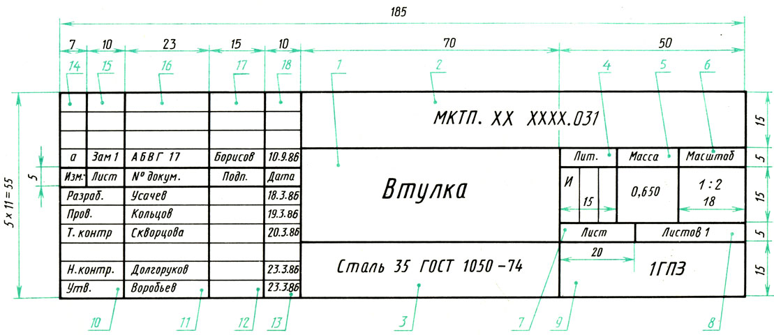
In the columns of the main inscription (the column numbers in Figure 2.3 are shown in brackets) indicate:
Column 1 - name of the product; in accordance with GOST 2.109-73 “ESKD. Basic requirements for drawings" the name should be short and written in nominative case singular; The first place should be a noun, for example: “Gear wheel.” After the name of the product, enter the name of the document (in a smaller font), if this document is assigned a code, for example: “Valve. Assembly drawing".
Column 2 - designation of the document (see paragraph 1.3).
Column 3 - designation of the product material (the column is filled out only on working drawings of parts), when designating the material, be sure to indicate GOST. For example, “Steel 45 GOST 1050-88”.
Column 4 - letter assigned to the document (see paragraph 1.2.).
Column 5 - product weight.
Column 6 - scale according to GOST 2.302-68 “ESKD. Scale" (see paragraph 2.3.).
Column 7 - serial number of the sheet.
Column 8 - total number of sheets.
Column 9 - indicates the group number, for example, “gr. 7C".
Column 11 - names of persons signing the document.
Column 12 - signatures of persons signing the document.
Column 13 - date of signing of the document.
Column 14 - duplicates Column 2 (document designation), but rotated 180°.
Date: 2010-04-29
Where does the drawing begin?
Just as a theater begins with a hanger, the execution of a drawing begins with drawing the frame, after which the main inscription of the drawing is drawn. This is the same stamp in the lower right corner of the sheet measuring 185 mm by 55 mm. Here's what it looks like:
(by clicking on the drawing you will be able to view the title block of the drawing in a separate window in higher quality)
The following fields are usually used and filled in:
1 - name of the product (in educational drawings, teachers often suggest indicating the name of the topic, usually these are drawings on descriptive geometry).
The entry is made in the nominative singular case. If the name consists of two or more words, then the first word must be a noun, for example, “Through bushing”;
2 - document designation;
3 - scale;
4 - serial number of the sheet (the column is not filled in on documents made on one sheet);
5 - the total number of sheets of the document (the column is filled in on the first sheet);
6 - document letter;
7 - surnames; (in educational drawings, as a rule, opposite the column Developed, the student’s surname is indicated, and opposite the column Prov. and Approved, the surname of the teacher)
8 - signatures;
9 - date of signature of the document;
10 - name, index of the enterprise;
11 – designation of material (to be filled in on the drawings of parts).
If you are just starting to make drawings and you have difficulties filling out the stamp (usually these are columns 2,6,10,11) - do not worry, as a rule, teachers clearly explain what exactly they want to see and you can fill them out immediately before change. If you have a manual from your university, it is better, of course, to use the recommendations and fill out all the fields in advance.
All columns, except signatures and dates, are filled in in pencil in a standard font. It is necessary to pay attention to the fact that when drawing the main inscription, both main and thin solid lines are used. In this case, the main line in the title block of the drawing must be the same thickness as the main line in the drawing itself. Very often you can see drawings already made with a stroke, and at the same time the stamp is drawn with lines twice as thick (this happens because students draw the stamp easily and this makes the lines used more confidently. But do not forget that after this you will have to trace the main ones again lines on the drawing)
Here is an example of the location of the main inscription of the drawing on sheets A4 and A3:

or write down our phone number and tell your friends about us - someone is probably looking for a way to complete the drawings
or Create a note about our lessons on your page or blog - and someone else will be able to master drawing.
In my opinion, it’s not difficult, but I don’t understand how to write all this at the bottom of the drawing sheet?
Alena, you are right: this inscription is located in the lower right corner of the drawing. In the case of an A4 sheet (which is always positioned vertically), the inscription will be “just below”.
Cool lessons, and most importantly, you put everything in order, unlike my teacher, who throws everything into one pile that you can’t figure out. But I would like more lessons.
And I’m a drawing teacher, I have a paper version of the notes, but here I have a ready-made electronic one, which is always complicated by computer sketches. Thank you, nothing more.
Thank you, I have never seen a more clear, logical and complete explanation on the Internet!!!
Irina, it is very important to hear your opinion, because when writing the next lesson on engineering graphics, I always suffer from doubts: “Am I explaining the material clearly?” Your response added confidence, thank you!
Very good instructive lessons. Here are just the basic lessons that SHOULD be taught in schools..... alas, they were removed from general school education and replaced with physical education lessons. It's sad...
Thanks a lot! I missed the first lessons and didn’t understand anything about what kind of basic inscription they were talking about) Respect to the author;)
in column 1 write the name of the product and the name of the document GOST 2.104 The topic in column 1 is not written “Simple cut” - a very bad example for the name of the product “Walk-through sleeve”, “Rear panel”, “TV camera” - a better example
Ekaterina, your vigilance will serve more than one generation of students! I’ll write that, thanks for the review!
Thank you. For technical documentation on electrical circuits, there are several other stamps on the second and subsequent sheets. Expand the article. Thanks again.
thank you, but I would like to see the font sizes when filling out columns 2,11,10
I wouldn't take the issue of choosing fonts too seriously. Choose from the available range: 3.5-5-7-10. Just figure out which font will be clearer. And so that the inscription fits. It’s unlikely that anyone here will scold you. But you should avoid writing short inscriptions such as “Lid”, “Body” in a large column, in deliberately small print. It will look inorganic and even disrespectful to some extent. In such cases, I would recommend using a font with a height of at least 7 mm, and preferably 10.
I need to draw a title page where it says “graphic work” and below everything that is supposed to be drawn, only the margins and the sides of the frame, also in the lower right corner there is a frame measuring 18 in length, 5 in height, and in the middle it should say “graphic” work" how to do it?
Add your comment.
Geometric drawing
with design rules
Drawings
To independent work by discipline
"Descriptive geometry, engineering
and computer graphics
for students in the field of study
0902 – Engineering mechanics
0909 – Devices
0925 – Automation and computer
integrated technologies
1002 – Ships and ocean engineering
daytime and correspondence forms training
Sevastopol
UDC 74 (075)
Geometric drawing with rules for drawing up drawings: Guidelines for independent work in the discipline “Descriptive geometry, engineering and computer graphics” for students in the field of study 0902 - engineering mechanics, 0909 - instruments, 0925 - automation and computer-integrated technologies, 1002 - ships and ocean engineering full-time and correspondence courses / Comp. Medved A.F., Sereda V.G., Smirinskaya N.Ya. – Sevastopol: SevNTU Publishing House, 2005. - 38 p.
The guidelines are developed with the aim of:
Familiarization with the description of the graphic composition of technical documentation (basic rules for the design of drawings);
Outlines of the techniques of some geometric constructions when performing individual tasks on the topic “Geometric drawing”.
Guidelines and assignments are developed based on work program“Descriptive geometry, engineering and computer graphics” in accordance with curriculum training of specialists.
The guidelines were reviewed and approved at a meeting of the Department of Descriptive Geometry and Graphics (Minutes No. 4 of December 3, 2003)
Approved by the educational and methodological center of SevNTU as methodological instructions.
Reviewer: Kharchenko A.O., Ph.D. tech. Sciences, Professor of the Department of Mechanical Engineering and Transport, Honored Inventor of Ukraine
| Introduction…………………………………………………………….. | |
| 1. rules for drawing up……………….. | |
| 1.1. Formats……………………………………………………………… | |
| 1.2. Scale……………………………………………………………….. | |
| 1.3. Lines……………………………………………………. | |
| 1.4. Fonts……………………………………………………………. | |
| 1.5. Main inscription……………………………………. | |
| 1.6. Graphic designations of materials………………... | |
| 1.7. Applying dimensions……………………………………. | |
| 2. Geometric constructions………………….. | |
| 2.1. Dividing a line segment……………………………….. | |
| 2.1.1. Dividing a segment in half…………………………… | |
| 2.1.2. Dividing a segment into equal parts…………………… | |
| 2.1.3. Dividing a segment into proportional parts……… | |
| 2.2. Dividing an angle into two equal parts…………………….. | |
| 2.3. Dividing a circle into equal parts………………… | |
| 2.4. Construction of a triangle……………………………… | |
| 2.5. Construction of the slope…………………………………….. | |
| 2.6 Constructing a taper………………………………. | |
| 2.7. Pairings………………………………………………………... | |
| 2.7.1. Conjugation of two straight lines……………………. | |
| 2.7.2. Conjugation of a straight line with an arc of a circle...... | |
| 2.7.3. Conjugation of two arcs of circles..………………... | |
| 3. Construction of curved lines……………………... | |
| 3.1. Construction of an oval……………………………………….. | |
| 3.2 Construction of an ellipse……………………………………... | |
| 3.3. Construction of a parabola……………………………………... | |
| 3.4. Construction of a hyperbola…………………………………. | |
| 4. Construction of profiles…………………………….. | |
| 4.1. Construction of a channel…………………………………... | |
| 4.2. Construction of an I-beam…………………………………… | |
| 5. Construction of the hook…………………………………. | |
| 6. instructions for completing the task…………... | |
| Conclusion……………………………………………… | |
| Bibliography……………………… |
Introduction
The development of modern equipment, machines, mechanisms, devices and other products is difficult without knowledge of drawing, which is necessary for every specialist involved in the design of equipment, its manufacture, assembly, installation, adjustment and control.
The goal of the work is to master the basic rules for drawing up drawings and master the technique of geometric constructions.
The study of mechanical engineering drawing begins with the rules for drawing up drawings, which are set out in the following standards: GOST 2.104-68. Basic inscriptions; GOST 2.301-68. Formats; GOST 2.302-68. Scale; GOST 2.303-68. Lines. GOST 2.304-81. Drawing fonts; GOST 2.306-68. Designations of graphic materials and rules for their application on drawings; GOST 2.307-68. Drawing dimensions and maximum deviations.
Students complete the task in the amount of two sheets of A3 format (420x297) - “ Title page" and "Geometric constructions". The task options are given in the tables.
Samples of completed tasks are shown in the pictures.
drawing rules
Technical documentation of any purpose and content has a single graphic composition: format, lines, fonts, main inscription, graphic designations of materials.
1.1. Formats
Sheet formats are determined by the dimensions of the outer frame made with a thin line. The inner frame of the drawing, limiting the working field, is made as a solid main line at the distances from the outer frame indicated in Figure 1.
The designation and dimensions of the main formats are given in Table 1.
Table 1 - Main formats
The dimensions of derivative formats are formed by multiplying the short side of the main format, for example, A3x5 is a derivative format of A3 format, the dimensions of which are: length - L = (5x297) + 1) = 1486 mm, and width B = 420 mm.
The scale in the drawing is indicated in the column provided for this and is indicated, for example, as 1:1 or 2:1 or 1:5. If one of the images is made on a scale different from that indicated in the main inscription, then next to the inscription relating to this image its scale is indicated (in brackets without the letter M), for example A-A (4: 1) or B (1: 2) . Sometimes several products (parts) are drawn on training drawings, indicating the name of the product above its image. If one of the products is made on a scale that does not coincide with the scale indicated in the main inscription, then the scale is indicated in parentheses next to the name of the product, for example, Hook (2:1).
When making drawings, lines are used, the design and thickness of which must comply with GOST 2.303-68 (Table 3).
In educational drawings, the main lines (visible contour lines) should be given a thickness of S = (0.8...1.0) mm, dashed lines (invisible contour lines) - 0.4...0.5 mm, open lines - 1.5S, and the remaining lines - 0.25…0.3 mm. Students should learn to distinguish the thickness of lines with an accuracy of 0.1...0.15 mm. As a rule, training drawings are first made with thin but clearly distinguishable lines. The required thickness of the lines is given when tracing.
Table 3 - Drawing lines according to GOST 2.303-68
The strokes and spacing between strokes should be equal accordingly.
Dot-dash and center lines should be replaced with solid thin ones if the diameter of the circle in the image is less than 12 mm. Lines with strokes must intersect and end with strokes.
An example of using lines in a drawing is shown in Figure 2.
Figure 3 - Font types
 |
An example of writing letters and numbers of type B with a slope of 75 0 is shown in Figure 4.
Figure 4 – Writing letters and numbers
Table 4 – Type B font sizes, mm
| Font size | 2,5 | 3,5 | 5,0 | 7,0 | 10,0 | 14,0 | 20,0 | |
| Height capital letters, h | 2,5 | 3,5 | 5,0 | 7,0 | 10,0 | 14,0 | 20,0 | |
| Height of lowercase letters | 1,8 | 2,5 | 3,5 | 5,0 | 7,0 | 10,0 | 14,0 | |
| Distance between letters, a | 0,5 | 0,7 | 1,0 | 1,4 | 2,0 | 2,8 | 4,0 | |
| Minimum line pitch, b | 4,3 | 6,0 | 8,5 | 12,0 | 17,0 | 24,0 | 34,0 | |
| Minimum distance between words, e | 1,5 | 2,1 | 3,0 | 4,2 | 6,0 | 8,4 | 12,0 | |
| Font line thickness, d | 0,25 | 0,35 | 0,5 | 0,7 | 1,0 | 1,4 | 2,0 | |
| Width of capital letters and numbers | Zh, Sh, Shch, F, b | 2,0 | 2,8 | 4,0 | 5,6 | 8,0 | 11,2 | 16,0 |
| A, D, M, X, S, Y | 1,8 | 2.5 | 3,5 | 4,9 | 7,0 | 9,8 | 14,0 | |
| G, W, E, S, 1, 2, 3, 4, 5, 6, 7, 8, 9, 0 | 1,3 | 1,8 | 2,5 | 3,5 | 5,0 | 7,0 | 10,0 | |
| Other letters | 1,5 | 2,1 | 3,0 | 4,2 | 6,00 | 8,4 | 12,0 | |
| Lowercase letter width | WITH | 1,0 | 1,4 | 2,0 | 2,8 | 4,0 | 5,6 | 8,0 |
| T, F, Sh, Sh, F | 1,8 | 2,5 | 3,5 | 5,0 | 7,0 | 10,0 | 14,0 | |
| M, Y, Yu | 1,5 | 2,1 | 3,0 | 4,2 | 6,00 | 8,4 | 12,0 | |
| Other letters | 1,3 | 1,8 | 2,5 | 3,5 | 5,0 | 7,0 | 10,0 |
Capital letters Latin alphabet A, B, C, E, K, M, O, P, T are executed as capital letters Russian alphabet A, B, C, E, K, M, O, P, T, respectively.
Lowercase letters of the Latin alphabet a, c, e, o, p are executed as lowercase letters of the Russian alphabet a, s, e, o, p, respectively.
1.5. Main inscription
The main inscription is a part of the drawing that contains significant information about the product depicted in the drawing itself. The main inscription consists of columns drawn with solid thick and thin lines in accordance with GOST 2.303-68 in the dimensions indicated in Figure 5. On training drawings, only the columns indicated by numbers in brackets are filled in.
In column 1 (Figure 5) and additional frame (Figure 6) the designation of the drawing is applied, consisting of a group of letters and numbers separated from each other by dots, for example, SNTU.101500.001, where SNTU is the abbreviated name of VUZ "a; 1 is the number of the settlement graphic task; 015 – option number; 001 – task number.
Column 2 indicates the name of the product in accordance with GOST 2.109-73. The name is written in the nominative singular case. If the name consists of several words, then the noun is placed first, for example: “Union nut.”
Column 3 indicates the scale at which the product image is drawn. In columns 4 and 5 - the name and signature of the student, respectively, and in column 6 - the date the drawing was signed by the student. In columns 7 and 8 - the name and signature of the teacher who accepted the drawing, and in column 9 - the date the drawing was signed by the teacher.
Column 10 is filled in only on drawings of parts. It indicates the designation of the material from which the part will be made, for example, Article 3 of GOST 380-94, where Article 3 is the grade of material and the GOST number, which specifies the requirements for the quality of the material.
The serial number of the sheet (column 11) is indicated if the drawing (task) is made on two or more sheets. On documents
|

Figure 5 – Title block
consisting of one sheet, column 11 is not filled in. In column 12, the number of sheets is indicated only on the first sheet.
Column 13 indicates the name of the department and group number, for example: “Department of NG and G, group ED 12d.”
The title block is located in the lower right corner of the drawing. For A4 format it is located only along the short side of the sheet(Figure 6a), and for other formats - both along the long (Figure 6b) and along the short side of the sheet (Figure 6c).
In the drawings, in addition to the main inscription, an additional frame is drawn, rotated to:
180 0 for format A4 (Figure 6a) and for formats larger than A4 when the main inscription is located along the long side (Figure 6b);
 |
- 90 0 for formats larger than A4 when the main inscription is located along the short side (Figure 6c).
Figure 6 – Location of the main inscription and additional frame in the drawings
All inscriptions in columns are made in type B drawing font with a height of: 10 mm - column 1; 7 mm - column 14, 5 mm - columns 2, 3 and 13.
The remaining graphs are made in size 2.5 mm. The inscription in the additional frame is rotated to:
180 0 for format A4 (Figure 6a) and for formats larger than A4 when the main inscription is located along the long side (Figure 66);
90 0 for formats larger than A4 when the title block is located along the short side (Figure 6c).
1.6. Graphic images of materials
When making cuts and sections, graphic designations of materials must comply with GOST 2.306-68 “Designations of graphic materials and rules for their application in drawings.” Table 5 shows graphic images of materials most often found when performing mechanical engineering drawing tasks.
Table 5 – Graphic images of materials
Hatching lines are drawn as a continuous thin line in increments of up to 10 mm, depending on the hatching area. The recommended hatching pitch is 1...3 mm. The frequency and angle of hatching must be the same for all sections of the same part, made to the same scale.
Narrow cross-sectional areas, the width of which in the drawing does not exceed 2 mm, may be shown blackened, leaving gaps between adjacent sections of at least 0.8 mm (Figure 9).
Figure 8 – Hatching Figure 9 – Hatching of adjacent adjacent parts of parts with narrow cross-sectional areas
1.7. Applying dimensions
The rules for applying dimensions on drawings are determined by GOST 2.307-68.
Size is numeric value linear or angular magnitude of the product or its elements in selected units.
Linear dimensions on the drawings they are indicated in millimeters without indicating units of measurement.
In order to organize the sizes, rounded numbers are accepted according to GOST 6636-69 “Normal linear dimensions”.
Angular dimensions indicated in degrees, minutes, seconds, for example 30 / , 2 0 , 2 0 30 / , 2 0 30 / 15 // , or as a ratio of two legs right angle, for example, 1:8.
The total number of dimensions in the drawing should be minimal, but sufficient for the manufacture and control of the product.
The size is applied in the drawing only once and in the image where the shape of this part of the part is better read. It is not allowed to repeat the dimensions of one element in different images.
Dimensions in the drawings are indicated by dimensional numbers, extension and dimension lines. When applying the size of a straight segment, the dimension line is drawn parallel to this segment, and the extension lines are perpendicular to the dimension line.
When applying the size of an angle, the dimension line is drawn in the form of an arc with the center at its vertex, and the extension lines are drawn radially. When applying the size of a circular arc, the dimension line is drawn concentrically with the arc itself, and the extension lines are drawn parallel to the bisector of the angle.
The dimension line is limited by arrows whose sharp ends abut the corresponding extension lines. It is allowed to draw dimension lines to the lines of the visible contour, axial, center and other lines. Extension lines should extend beyond the ends of extension lines by 1...5 mm.
The distance of the dimension line from the contour line parallel to it must be at least 10 mm, and between dimension lines at least 7 mm.
It is allowed to draw dimension lines with a break when indicating the size of the diameter of the circle, while the break of the dimension line is made further center line, and when drawing dimensions from the base, if it is not shown in the drawing. When depicting a product with a gap, the dimension line is not interrupted.
The signs accompanying the dimensional numbers are given in Table 6.
Table 6 - Example of using symbols
The dimensional number of the sphere diameter is preceded by a ¡ sign, for example ¡ Ø 20 – a sphere with a diameter of 20 mm.
When using break lines in a drawing, dimension lines should be drawn completely, at the same time. Dimensions must correspond to actual sizes.
When applying dimensions it is not allowed:
Place dimensions from the lines of the invisible contour;
Use contour, axial, center and extension lines as dimension lines;
Divide or cross out dimensional numbers with any lines;
Apply size numbers at the intersection of two lines.
2 . Geometric constructions
The contours of the depicted parts are formed by lines - straight, box and pattern curves. When drawing images, the following constructions are used:
Division of segments and angles;
Dividing a circle into equal parts;
Line mates;
Construction of slope and taper.
2.1. Division of a line segment
2.1.1. Dividing a segment in half
Dividing the segment in half is done as follows (Figure 10a):
Arcs are drawn from points A and B with radius R > 0.5AB until they intersect at points C and D;
A straight line is drawn through points C and D, which divides the segment in half (point E).
 |
Figure 10 – Division of a segment
2.1.2. Dividing a segment into equal parts
The segment is divided into equal parts as follows (Figure 10b):
From point A of segment AB, draw a straight line at an arbitrary angle and divide it into a given number of equal segments (points 1, 2, 3, C);
From points 1, 2, and 3, draw straight lines parallel to segment BC, until they intersect with segment AB at points 1", 2" and 3".
2.1.3. Dividing a segment into proportional parts
The segment is divided into proportional parts in the following sequence (Figure 10c):
From point A of segment AB, draw a straight line at an arbitrary angle and divide it into equal parts, for example, three;
Point C is connected to point B;
From point D draw a straight line parallel to segment BC.
2.2. Dividing an angle into two equal parts
Dividing the angle into equal parts is performed in the following sequence (Figure 11):
From the vertex of angle B, an arc of arbitrary radius R is drawn until it intersects with the sides of the angle at points D and C;
Arcs are drawn from points D and C with radius R 1 until they intersect at point K;
Connect points B and K (segment BK divides the angle in half).
 |
Figure 11 – Dividing an angle Figure 12 – Dividing a circle
2.3. Dividing a circle into equal parts
An example of dividing a circle into equal parts is shown in Figure 12.
To the right of the CD axis the division of the circle into three, six and twelve parts is shown, for which:
From point A of radius R, a circle draws an arc until it intersects the circle at points F and E. The segment FE cuts off a third of the circle, AF cuts off a sixth, and DF cuts off a twelfth of the circle.
On the left, above the AB axis, the division of the circle into five and ten parts is shown (above the AB axis), for which:
From point A of radius R, a circle draws an arc until it intersects the circle at points F and E;
From point E a perpendicular is built until it intersects with the axis AB (point) O 1;
From point O 1 with radius R 1 =O 1 C, draw an arc until it intersects with
axis AB (point M). The segment CM divides the circle into five, and the segment OM into ten equal parts.
Below the AB axis on the left is shown the division of the circle into four and eight equal parts, for which:
Connect points B and D;
Divide segment BD in half (see paragraph 2.1.1);
From the center O, draw a perpendicular bisector to the intersection with the circle (point K). Segment BD divides the circle into four, and segment KD into eight equal parts.
2.4. Construction of a triangle
An example of constructing a triangle using three given sides is shown in Figure 13.
|

Figure 13 – Construction of a triangle
Arcs are drawn from the ends of the side AC of the triangle with radii R = n and R 1 = m until they intersect at point B. The resulting point is connected to points A and C.
2.5. Construction of the slope
Slope i straight line AC relative to straight line AB is called the tangent of the angle between these straight lines, i.e. i = (h/l) = tga, Where h – difference between applicate ends of segment AC; l – difference in abscissa of segment AB (Figure 14).
The slope in the drawing in accordance with GOST 2.307 - 68 is indicated using a leader line, on the shelf of which the sign and value of the slope are applied.
The slope is indicated by the sign “Р”, and its value is expressed as a fraction, percentage and degrees, for example, Р 1:5, Р 20%, Р 15 0. The location of the slope sign must correspond to the line being determined: one of the straight lines of the sign must be parallel to the leg (AB), and the other is inclined at an angle of 30 0 to it, while the tip of the sign is always directed towards the slope.
|


Figure 14 – Definition Figure 15 – Slope designation
dividing the slope
2.6. Constructing a taper
Taper C is the ratio of the diameter of the circle of the base of a right cone to its height C = D/2H = tga/2 (Figure 16).
The taper in the drawing in accordance with GOST 2.307 - 68 is indicated using a leader line, on the shelf of which the sign and value of the taper are applied.
Figure 16 – Definition Figure 17 – Designation
taper taper
The construction of a truncated cone with a given diameter of the larger base D, height H and taper equal to 1:4 (Figure 18) is performed in the following sequence:
We plot the height of the cone H=OO 1 on the axis of symmetry;
Through point O we draw a perpendicular, on which we plot the diameter of the large base D=BC symmetrically from the axis;
From point O along the axis OO 1 we lay off four equal segments of arbitrary length OA=4a;
From point O, symmetrically from the axis, we lay off the segment a=FE;
By connecting points F and E with point A, we obtain an auxiliary cone with a taper of 1:4;
Through points B and C we draw straight lines parallel to the generators of the auxiliary cone until they intersect with a perpendicular drawn through point O 1. The resulting points K and L limit the size of the small base of the truncated cone.
2.7. Mates
The outline of many parts and nodes consists of lines that smoothly transition into one another, called conjugation. From the variety of possible connections, the following can be distinguished:
Conjugation of two straight lines with a circular arc;
Conjugation of a straight line with a circular arc using another circular arc;
Conjugation of two arcs of a circle using a third arc.
|

|
Figure 18 – Construction Figure 19 – Conjugation of the taper of the sides of the angle
2.7.1. Pairing two straight lines
The pairing of two sides of an angle with a circular arc (Figure 19) is performed as follows:
Parallel to the sides of the angle AB and BC at a distance equal to the radius of the arc R, draw straight lines l and m until they intersect at point O;
From point O, perpendiculars are lowered onto the mating sides. Points D and E are mate points;
From point O with radius R = OD = OE, draw an arc smoothly turning into straight lines.
2.7.2. Pairing a straight line with a circular arc
Let's consider two cases of pairing: external and internal.
The external conjugation of a straight line with a circular arc is performed as follows:
An arc with radius R 2 =R+R 1 is constructed from center O, where R 1 is the radius of conjugation;
The center O 1 of the interface is determined as the result of the intersection of a circular arc of radius R 2 with straight line m;
From the center O 1, a conjugation arc AB with radius R 1 is constructed.
The internal conjugation of a straight line with a circular arc is performed as follows:
From the given center of a given circular arc, an arc of radius R 2 =R-R 1 is constructed, where R 1 is the conjugation radius;
At a distance R 1 from a given line n, a parallel line m is drawn;
From the resulting center O 1, a conjugation arc AB with radius R 1 is constructed.
Figure 20 – Conjugation of a circular arc with a straight line
2.7.3. Pairing two arcs of a circle
There are external, internal and mixed conjugation of two arcs with a third arc. In all three cases, it is necessary to determine the position of the center of the mating arc O 2 and the mating points A and B.
External pairing (Figure 21a) is performed as follows:
From the centers of arcs of circles O and O 1 with radii R 3 =R+R 2 and R 4 =R 1 +R 2, respectively, draw arcs until they intersect at point O 2;
|

Figure 21 – Conjugation of two circular arcs
An example of internal pairing is shown in Figure 21b):
From the centers of arcs of circles O and O 1 with radii R 3 = R 2 -R and R 4 =R 2 - R 1 we draw arcs until they intersect at point O 2 ;
We connect the center of conjugation O 2 with the centers of arcs of circles with straight lines O 2 O and O 2 O 1;
From the interface center O 2 with radius R 2 we draw an arc between the interface points A and B.
Mixed conjugation (Figure 21c) is performed as follows:
From the centers of arcs of circles O and O 1 with radii R 3 =R+R 2 and R 4 =R-R 2, respectively, draw arcs until they intersect at point O 2 ;
We connect the center of conjugation O 2 with the centers of arcs of circles with straight lines O 2 O and O 2 O 1;
From the interface center O 2 with radius R 2 we draw an arc between the interface points A and B.
Drawings are made on sheets of strictly defined dimensions established by GOST 2.301-68 (ST SEV 1181-78). This makes them easier to store.
Format drawing is indicated by a letter and a number, for example A3, A4.
Sheet formats are determined by the dimensions of the outer frame (Fig. 16). The framing line (format frame) is applied at a distance of 5 mm from the outer frame (copy trim line) in the direction of the drawing margin for A3 and A4 formats and at a distance of 5 to 10 mm for other formats. The thickness of the framing line is at least 0.7 mm.
The smallest format is A4; its size is 210 x 297 mm. Most often you will use A4 format.
If necessary, it is allowed to use A5 format with side dimensions of 148 x 210 mm.
Each designation corresponds to a specific size of the main format.
For example, A3 format corresponds to a sheet size of 297 x 420 mm.
The table shows the designations and sizes of the main formats.
From the given sizes of the formats it follows that a smaller format can be obtained by dividing the larger one in half parallel to the smaller side. In addition to the main ones, the use of additional formats is allowed. They are obtained by enlarging the short sides of the main formats by an amount that is a multiple of their dimensions.
Training drawings are made in formats corresponding to the dimensions in accordance with GOST 2.301-68.
Frame. Each drawing has a frame that limits the area of the drawing. The frame is drawn with solid thick main lines: on three sides at a distance of 5 mm from the edge of the sheet, and on the left - at a distance of 20 mm; a wide strip is left for filing drawings.
Main inscription. In the lower right corner of the drawing is placed the main inscription, which contains a number of information about the part depicted in the drawing.
According to the standard, the main inscription is placed along the long or short side of the sheet, except for A4 format, where the inscription is placed along the short side (see Fig. 16). In educational drawings, in order to save paper, the main inscription can also be placed along the long side of the A4 sheet.
In Fig. Figure 17 shows the form and gives an example of filling out the title block for production drawings.
Read the main inscription carefully and write down in your notebook:
a) name of the product;
b) what material the part is made of;
c) the mass of the product (it is indicated in kilograms);
d) drawing scale;
e) the name of the persons who developed, checked and approved the drawing;
f) date of approval.
This information is given in the columns marked in Fig. 17 respectively with numbers 7, 3, 5, 6, 10-13.
Column 2 indicates the designation (number) of the drawing. The same designation, rotated 180°, is placed in the left top corner drawing, which makes it easier to find drawings that are not filed in an album, but stored in bulk.
In column 4, enter the letter of the drawing. Drawings for single production are assigned the letter I, installation series - A, serial or mass production - B.
In column 7, write down the serial number of the sheet. If the drawing consists of one sheet, then column 7 is not filled in.
Column 8 indicates the total number of sheets of the document.
Column 9 contains the name or distinctive index of the enterprise that issued the drawing.
Columns 14-18 are a table of changes. Changes (corrections) in the drawing are allowed to be made only by the enterprise holding the original drawing in accordance with the rules established by GOST 2.503-74 (ST SEV 1631-79). In this case, in column 14, enter the letter of the change (letters a, b, vit. d.), which is repeated next to the change made. Columns 15-18 are also filled in. Please note that if the change is not formalized in this way, then the drawing cannot be used.
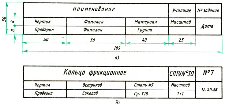
For drawings performed as a training task, it is allowed to place a simplified title block, the dimensions and example of filling of which are shown in Fig. 18, a and b.
Letters and numbers in the main inscription, as well as in the entire drawing, are usually written in a drawing font, which is given in the appendix for reference. I and II.
Answer the questions?

1. What are the dimensions of the A4 sheet?
2. How many A4 sizes are there in A3 size? In A2 format?
3. At what distance from the edges of the sheet is the frame drawn?
4. Where on the drawing is the main inscription located?
5. What information is indicated in the title block on student drawings?
6. What is the difference in drawing center lines for circles with a diameter of up to 12 mm and more than 12 mm?
Tasks for § 3
Exercise 11
Copy the following format sizes into your notebook. Place the designations of these formats on the right.
Exercise 12
Draw in a notebook the shape and dimensions of the simplified title block for student drawings (Fig. 18, a).
Exercise 13

Place a frame on an A4 sheet of paper and draw the main inscription, placing it along the short side (according to Fig. 16).