How sizes are set. General rules for dimensioning drawings
Sometimes, in tasks on descriptive geometry or work on engineering graphics, or when performing other drawings, it is required to build a slope and a cone. In this article, you will learn about what slope and taper are, how to build them, how to correctly mark them on the drawing.
What is a slope? How to determine slope? How to build slope? Designation of the slope on the drawings according to GOST.
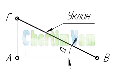
slope. Slope is the deviation of a straight line from a vertical or horizontal position.
Slope definition. The slope is defined as the ratio opposite leg angle right triangle to the adjacent leg, that is, it is expressed by the tangent of the angle a. The slope can be calculated using the formula i=AC/AB=tga.
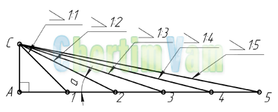
Building a slope. The example (figure) clearly demonstrates the construction of a slope. To build a 1:1 slope, for example, you need on the sides right angle set aside arbitrary but equal segments. Such a slope will correspond to an angle of 45 degrees. In order to build a slope of 1: 2, you need to set aside a segment horizontally equal in value to two segments laid down vertically. As can be seen from the drawing, the slope is the ratio of the opposite leg to the adjacent leg, that is, it is expressed by the tangent of the angle a.
Designation of the slope in the drawings. The designation of slopes in the drawing is carried out in accordance with GOST 2.307-68. In the drawing, indicate the magnitude of the slope using the leader line. On the shelf of the leader line, a sign and the magnitude of the slope are applied. The slope sign must correspond to the slope of the line being determined, that is, one of the straight lines of the slope sign must be horizontal, and the other must be inclined in the same direction as the line of slope being determined. The slope angle of the sign line is approximately 30°.
What is taper? Formula for calculating taper. The designation of the taper in the drawings.
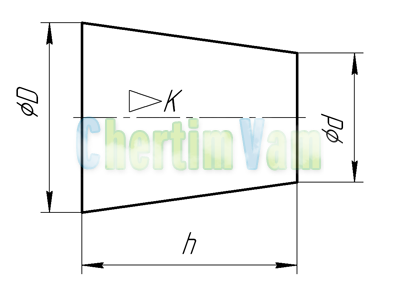
Taper. Taper is the ratio of the diameter of the base of the cone to the height. The taper is calculated by the formula K=D/h, where D is the diameter of the base of the cone, h is the height. If the cone is truncated, then the taper is calculated as the ratio of the difference in the diameters of the truncated cone to its height. In the case of a truncated cone, the conicity formula will look like: K \u003d (D-d) / h.
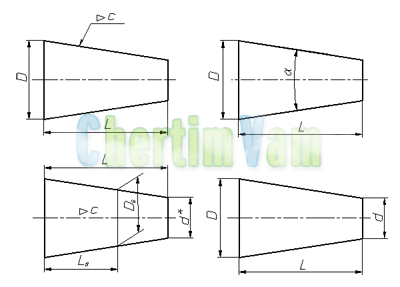
Designation of taper in the drawings. The shape and size of the cone is determined by applying three of the following dimensions: 1) the diameter of the large base D; 2) diameter of the small base d; 3) diameter in a given cross section Ds having a given axial position Ls; 4) cone length L; 5) cone angle a; 6) taper p. Also on the drawing it is allowed to indicate additional dimensions as a reference.
The dimensions of standardized cones do not need to be indicated on the drawing. It is enough to show in the drawing symbol taper according to the relevant standard.
The taper, like the slope, can be indicated in degrees, as a fraction (simple, as a ratio of two numbers or decimal), as a percentage.
For example, a 1:5 taper could also be referred to as a 1:5 ratio, 11°25’16”, decimal 0.2 and in percentage 20.
For tapers used in mechanical engineering, OCT/BKC 7652 specifies a range of normal tapers. Normal taper - 1:3; 1:5; 1:8; 1:10; 1:15; 1:20; 1:30; 1:50; 1:100; 1:200. Also in can be used - 30, 45, 60, 75, 90 and 120 °.
The rules for applying dimensions to drawings are established by GOST 2.307-68. The number of dimensions in the drawing should be minimal, but sufficient for the manufacture of the product. Each dimension is indicated on the drawing only once. The distance from the first contour line to the dimension line is at least 10 mm, between the dimension lines is at least 7 mm. When staging a large number dimensions, it is necessary to avoid the intersection of dimension and extension lines.
Dimensions are divided into linear and angular. Dimensions include extension lines, dimension lines, dimension numbers (Fig. 3.1). Extension and dimension lines are depicted as thin solid lines in a standard font of size 3.5 or 5. Dimension numbers are applied above the dimension lines at a distance of 1 ... 1.5 mm. Linear dimensions in the drawings are indicated in millimeters without indicating units of measurement. Angular dimensions in the drawings are indicated in degrees, minutes, seconds.
Figure 3.1
The basis for determining the size of the depicted product and its elements are the dimensional numbers printed on the drawing. The exception is the cases provided for in GOST 2.414-75; GOST 2.417-78; GOST 2.419-68, when the size of the product or its elements is determined from images made with a sufficient degree of accuracy.
The basis for determining the required accuracy of the product during manufacture are indicated on the drawing limit deviations dimensions, as well as limiting deviations of the shape and location of surfaces.
The total number of dimensions in the drawing should be minimal, but sufficient for the manufacture and control of the product.
Dimensions that are not subject to execution according to this drawing and are indicated for greater ease of use of the drawing are called reference. Reference dimensions in the drawing are marked with a “*”, and in the technical requirements they write: “* Dimensions for reference”. If all dimensions in the drawing are for reference, they are not marked with an “*” sign, and in the technical requirements they write: “Dimensions for reference”.
On construction drawings, reference dimensions are noted and specified only in cases provided for in the relevant documents approved in the prescribed manner.
Reference sizes include the following:
a) one of the sizes of a closed dimensional chain. Limit deviations of such dimensions are not indicated in the drawing (Fig. 3.2);
b) dimensions transferred from the drawings of blank products (Fig. 3.3);
c) dimensions that determine the position of the elements of the part to be processed on another part (Fig. 3.4);
d) dimensions on assembly drawing, which determine the limiting positions of individual structural elements, for example, the piston stroke, the stroke of the valve stem of an internal combustion engine, etc .;
e) dimensions on the assembly drawing, transferred from the drawings of parts and used as installation and connecting ones;
e) overall dimensions on the assembly drawing, transferred from the drawings of parts or being the sum of the dimensions of several parts;
g) the dimensions of parts (elements) from sectional, shaped, sheet and other rolled products, if they are fully determined by the designation of the material given in column 3 of the main inscription.
Figure 3.2
Figure 3.3
Figure 3.4
Notes:
1. Reference dimensions indicated in subparagraphs b, c, d, f, g, it is allowed to apply both with limiting deviations and without them.
2. Mounting and connecting dimensions are those that determine the dimensions of the elements by which this product is installed at the installation site or attached to another product.
3. Dimensions are called dimensions that determine the limiting external (or internal) outlines of the product.
4. On the drawings of products, for dimensions that are technically difficult to control, the sign "*" is applied, and in the technical requirements the inscription "Dimensions provided. instr.".
Note. The indicated inscription means that the fulfillment of the size specified by the drawing with the maximum deviation must be guaranteed by the size of the tool or the corresponding technological process.
At the same time, the dimensions of the tool or the technological process are checked periodically in the process of manufacturing products.
Tool inspection frequency or technological process installed by the manufacturer together with the customer's representative.
It is not allowed to repeat the dimensions of the same element in different images, in technical requirements, in the main inscription and in the specification. The exception is the reference dimensions given in subparagraphs b And well.
If in the technical requirements it is necessary to refer to the size printed on the image, then this size or the corresponding element is indicated by a letter, and in the technical requirements an entry similar to that shown in Fig. 3.5.
1 Axes parallelism tolerance A and B - 0.05 mm
2 Size difference B on both sides - more than 0.1 mm
Figure 3.5
Dimensions may be repeated on construction drawings.
Linear dimensions and their maximum deviations in the drawings and specifications are indicated in millimeters, without indicating the unit of measurement.
For dimensions and maximum deviations given in the technical requirements and explanatory inscriptions on the drawing field, the units of measurement must be indicated.
If the dimensions on the drawing must be indicated not in millimeters, but in other units of measurement (centimeters, meters, etc.), then the corresponding dimensional numbers are recorded with the designation of the unit of measurement (cm, m) or indicated in the technical requirements.
On construction drawings, units of measurement in these cases may not be indicated if they are specified in the relevant documents approved in the prescribed manner.
Angular dimensions and limit deviations of angular dimensions are indicated in degrees, minutes and seconds with the designation of the unit of measurement, for example: 4 °; 4°30"; 12° 45"30"; 0°30"40"; 0°18"; 0°5"25"; 0°0"30"; 30° ± 1°; 30° ± 10".
For dimensional numbers apply simple fractions not allowed, except for sizes in inches.
The dimensions that determine the location of the mating surfaces are affixed, as a rule, from constructive ones without taking into account the possibilities of performing and controlling these dimensions.
When the elements of the object (holes, grooves, teeth, etc.) are located on the same axis or on the same circle, the dimensions that determine them mutual arrangement applied in the following ways:
From a common base (surface, axis) - according to fig. 3.6, a and b;
By setting the sizes of several groups of elements from several common bases- according to fig. 3.6 b;
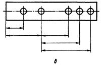
By setting the dimensions between adjacent elements (chain) - according to fig. 3.7.
General rules dimensioning drawings
The standard (GOST 2.307-68) establishes the rules for applying dimensions to drawings.
Linear dimensions in the drawings are given in millimeters without designation of units of measurement (mm). With other units of measurement (centimeters, meters), dimensional numbers are written with the designation of units of measurement (cm, mi). Angular dimensions are indicated in degrees, minutes, seconds with the designation of units of measurement. The total number of dimensions in the drawings should be minimal, but sufficient for the manufacture and control of the product.
There are strictly defined rules for sizing. When applying the size of a straight segment, the dimension line is drawn parallel to this segment, and the extension lines are perpendicular to the dimension lines (Fig. 34, b). The extension lines go beyond the dimensional ones by 1-3 mm. The distance from the dimension line to the image outline must be at least 10 mm, and the distance between two adjacent dimension lines must be at least 7 mm.
Arrows are drawn at the ends of the dimension lines. The shape and dimensions of the arrow are shown in fig. 34, a. The size of the arrows must be the same throughout the drawing. Arrows with a lack of space can be replaced by serifs or dots (Fig. 35, b, c). It is allowed to put down the dimensions as shown in Fig. 34, city
Dimensional numbers are applied above the dimension line closer to the middle (Fig. 36).
When applying several parallel or concentric dimension lines, the dimension numbers above them are staggered (Fig. 37).
Rice. 36 Fig. 37
In the drawings, it is necessary to avoid the intersection of dimension and extension lines. If there is not enough space above the dimension line to apply the dimension number, then the dimensions are affixed as shown in Fig. 38.
In places where the dimension number is applied, the axial, center lines and hatching lines are interrupted (Fig. 39, a, b).
When drawing the dimensions of the arcs, a radius sign - R is placed in front of the dimension number. The height of the radius sign and the dimension number should be the same (Fig. 46, a). When drawing several radii from one center, the dimension lines of any two radii are not located on the same straight line (Fig. 40, b). At big size radius center is allowed to approach the arc. In such cases, the dimension line is shown with a break (Fig. 40, c).
When drawing the dimensions of circles, a diameter sign is put in front of the dimension number - Ø (Fig. 41). If there is not enough space on the drawing, the dimensions of the diameter are affixed as shown in Fig. 41, b.
The dimensions of several identical elements of the product are applied once, indicating their number on the leader shelf, fig. 42.
The dimensions of a square or square hole are plotted as shown in fig. 43.
The thickness of a flat part is indicated by the letter S followed by a dimension number (Fig. 44).
The length of the product is indicated by a small letter Latin alphabet- l (Fig. 45).
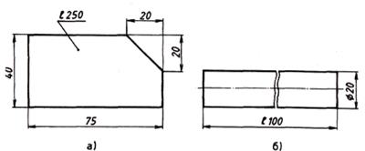
The application of the dimensions of the chamfer - the beveled edge of the rod, bar, hole - is carried out either by setting two linear dimensions (Fig. 46, b), or linear and angular dimensions(Fig. 46, c, d).
If there are several identical chamfers in the drawing, then the size is applied once as shown in fig. 46, c. This inscription means that two chamfers of 2 mm in size were removed at an angle of 45 °.
On the drawings it is necessary to put down the overall dimensions.
Overall dimensions are called dimensions that determine the limiting values \u200b\u200bof the external outlines of products. The overall dimensions include the dimensions of the length, width, height of the product.
dimensions there are always more than others, so they are placed farther from the image in the drawing than the rest.
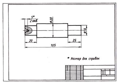
Reference dimensions are sometimes applied to the drawings. Dimensions applied on the drawing, but not subject to control, are called reference. In the drawing, they are marked with * (Fig. 47). At the location technical requirements(above the main inscription) make an entry: * - size for reference.
Scales
Scales are used to depict very large or too small products (aircraft, watches) in the drawings.
Scale is the ratio of the size of the image to the actual size of the object.
If the images in the drawings have the same dimensions as the actual dimensions of the part, it is considered that the drawings are made in full size, or on a scale of 1:1 (one to one). If the images in the drawing are larger than the actual dimensions of the part, then the magnification scale is used to build them. If the images in the drawing are smaller than the actual dimensions of the part, then a reduction scale is used to build them.
The standard (GOST 2.302-68) establishes:
Life size scale - 1:1.
Scale reduction - 1:2; 1:2.5; 1:4; 1:5; 1:10; 1:15; 1:20; 1:25; 1:40; 1:50; 1:75; 1:100; 1:200; 1:400; 1:500; 1:800; 1:1000.
Scales of increase - 2:1; 2.5:1; 4:1; 5:1; 10:1; 20:1; 40:1; 50:1; 100:1.
At any scale in the drawing, only actual dimensions are always applied. The scale is recorded in a special column of the main inscription according to the type 1:1; 1:2; 2:1, etc. The scale can be put on the drawing field only for those images that are made on a scale different from the scale declared in the title block. In this case, a record M 1: 2 is made above the image; M 2:1, etc.
Compare images made at different scales (Fig. 48).
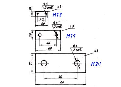
To build a 2:1 scale drawing of a part, you need to linear dimensions enlarge images twice. If it is necessary to perform an image on a scale of 1: 2, then the linear dimensions are halved. The dimensions of the corners do not change when the image scale is selected.
Questions and tasks
1. What determines the size of the drawing font?
2. What is equal to the angle slope of letters, numbers, characters of a drawing font?
3. What is the relative height and width of lowercase letters of the Russian alphabet of size No. 5.
4. What is the value of the distance between words for sizes 3.5 and 5.
5. What types of lines are used when making graphic images?
6. What line is used to depict the visible contour?
7. What line is used to draw extension and dimension lines?
8. What line is used to depict the axes of symmetry and center lines?
9. When is a solid thin line used?
10. In the drawing and visual representation, the lines are indicated by numbers (Fig. 49). Determine the type of lines and their purpose.
11. Explain why the main inscription is performed on the drawing. What information is included in the title block? Where is the title block placed on the drawing?
12. On which of the formats the main inscription of the drawing cannot be placed along the long side? What are the dimensions of this format?
13. In what units are linear dimensions expressed in engineering drawings?
14. How many millimeters should the extension lines protrude beyond the ends of the arrows of the dimension lines?
15. What is the minimum distance between parallel dimension lines?
16. What signs indicate the thickness and length of the product?
17. What dimensions are called overall?
18. What sign indicates the dimensions for reference?
19. What is scale?
20. What are the scales set by the standard?
21. What are scales for?
22. Where is the image scale indicated on the drawing?
23. Where and how is the scale of the image indicated if it differs from that indicated in the title block?