How to connect a car amplifier with your own hands. Tube sound amplifier
Having bought a good laptop or a cool phone, we rejoice at the purchase, admiring the many functions and speed of the device. But as soon as we connect the gadget to the speakers to listen to music or watch a movie, we understand that the sound produced by the device, as they say, “let us down.” Instead of full and clear sound, we hear an unintelligible whisper with background noise.
But don’t get upset and scold the manufacturers; you can solve the sound problem yourself. If you know a little about microcircuits and know how to solder well, then it will not be difficult for you to make your own audio amplifier. In our article we will tell you how to make a sound amplifier for each type of device.
At the initial stage of creating an amplifier, you need to find tools and buy components. The amplifier circuit is manufactured at printed circuit board using a soldering iron. To create microcircuits, use special soldering stations, which can be bought in the store. The use of a printed circuit board allows you to make the device compact and easy to use.
 Audio amplifier
 Do not forget about the features of compact single-channel amplifiers based on TDA series microcircuits, the main of which is the selection large quantity heat. Therefore, when designing the internal structure of the amplifier, try to prevent the microcircuit from coming into contact with other parts. For additional cooling of the amplifier, it is recommended to use a radiator grille to dissipate heat. The size of the grid depends on the model of the microcircuit and the power of the amplifier. Plan in advance a place for the heat sink in the amplifier case.
Another feature self-made The sound amplifier is low power consumption. This in turn allows you to use the amplifier in a car by connecting it to a battery or on the road using battery power. Simplified amplifier models require a current voltage of only 3 volts.
 Basic amplifier elements
 If you are a beginner radio amateur, then for more convenient work, we recommend that you use a special computer program- Sprint Layout. With this program you can independently create and view diagrams on your computer. Please note that creating your own scheme only makes sense if you have sufficient experience and knowledge. If you are an inexperienced radio amateur, then use ready-made and proven circuits.
Below we provide diagrams and descriptions different options sound amplifier:
Headphone amplifier
The sound amplifier for portable headphones is not very powerful, but consumes very little energy. This is an important factor for mobile amplifiers that are powered by batteries. You can also place a connector on the device for power supply via a 3 volt adapter.
 Homemade headphone amplifier
 To make a headphone amplifier you will need:
- Chip TDA2822 or analogue KA2209.
- Amplifier assembly diagram.
- Capacitors 100 uF 4 pieces.
- Headphone jack.
- Adapter connector.
- Approximately 30 centimeters of copper wire.
- Heat sink element (for a closed case).
 Headphone amplifier circuit
 The amplifier is manufactured on a printed circuit board or mounted. Do not use this type of amplifier pulse transformer, as it may cause interference. After manufacturing, this amplifier is capable of providing powerful and pleasant sound from a phone, player or tablet.
With one more option homemade amplifier for headphones, you can watch the video:
Sound amplifier for laptop
An amplifier for a laptop is assembled in cases where the power of the speakers built into it is not enough for normal listening, or if the speakers are out of order. The amplifier must be designed for external speakers up to 2 watts and winding resistance up to 4 ohms.
 Sound amplifier for laptop
 To assemble the amplifier you will need:
- Printed circuit board.
- Chip TDA 7231.
- 9 volt power supply.
- Housing for housing components.
- Non-polar capacitor 0.1 µF - 2 pieces.
- Polar capacitor 100 uF - 1 piece.
- Polar capacitor 220 uF - 1 piece.
- Polar capacitor 470 uF - 1 piece.
- Constant resistor 10 Kom - 1 piece.
- Constant resistor 4.7 Ohm - 1 piece.
- Two-position switch - 1 piece.
- Loudspeaker input jack - 1 piece.
 Audio amplifier circuit for laptop
 The assembly order is determined independently depending on the diagram. The cooling radiator must be of such a size that the operating temperature inside the amplifier case does not exceed 50 degrees Celsius. If you plan to use the device outdoors, then you need to make a case for it with holes for air circulation. For the housing, you can use a plastic container or plastic boxes from old radio equipment.
You can watch the visual instructions in the video:
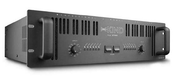
Sound amplifier for car radio
This amplifier for a car radio is assembled on a TDA8569Q chip; the circuit is not complicated and very common.
 Sound amplifier for car radio
 The microcircuit has the following declared characteristics:
- Input power is 25 watts per channel into 4 ohms and 40 watts per channel into 2 ohms.
- Supply voltage 6-18 volts.
- Reproducible frequency range 20-20000 Hz.
For use in a car, a filter must be added to the circuit to prevent interference generated by the generator and ignition system. The microcircuit also has protection against output short circuit and overheating.
 Audio amplifier circuit for car radio
 Referring to the diagram presented, purchase the necessary components. Next, draw the circuit board and drill holes in it. After this, etch the board with ferric chloride. Finally, we tinker and begin to solder the components of the microcircuit. Please note that it is better to cover the power paths with a thicker layer of solder so that there are no power drawdowns.
You need to install a radiator on the chip or organize active cooling using a cooler, otherwise the amplifier will overheat at increased volume.
After assembling the microcircuit, it is necessary to make a power filter according to the diagram below:
 Interference filter circuit
 The choke in the filter is wound in 5 turns, with a wire with a cross-section of 1-1.5 mm, on a ferite ring with a diameter of 20 mm.
This filter can also be used if your radio picks up interference.
Attention! Be careful not to reverse the polarity of the power supply, otherwise the microcircuit will burn out instantly.
You can also learn how to make an amplifier for a stereo signal from the video:
Transistor sound amplifier
As a circuit for a transistor amplifier, use the circuit below:
 Transistor audio amplifier circuit
 The scheme, although old, has a lot of fans, for the following reasons:
- Simplified installation due to the small number of elements.
- There is no need to sort transistors into complementary pairs.
- 10 watts of power, sufficient for living rooms.
- Good compatibility with new sound cards and players.
- Excellent sound quality.
Start assembling the amplifier with power supply. Separate the two channels for stereo with two secondary windings coming from the same transformer. On the breadboard, make bridges using Schottky diodes for the rectifier. After the bridges there are CRC filters consisting of two 33,000 uF capacitors and a 0.75 Ohm resistor between them. A powerful cement resistor is needed for the filter; at a quiescent current of up to 2A, it will dissipate 3 W of heat, so it is better to take it with a margin of 5-10 W. For the remaining resistors in the circuit, a power of 2 W will be enough.
 Transistor amplifier
 Let's move on to the amplifier board. Everything except the output transistors Tr1/Tr2 is on the board itself. The output transistors are mounted on radiators. It is better to first set up resistors R1, R2 and R6 as trimmers, unsolder them after all adjustments, measure their resistance and solder the final constant resistors with the same resistance. The setting comes down to the following operations - using R6, it is set so that the voltage between X and zero is exactly half of the voltage +V and zero. Then, using R1 and R2, the quiescent current is set - we set the tester to measure direct current and measure the current at the positive input point of the power supply. The quiescent current of an amplifier in class A is maximum and, in fact, in the absence of an input signal, all of it goes into thermal energy. For 8 ohm speakers, this current should be 1.2 A at 27 volts, which means 32.4 watts of heat per channel. Since setting the current can take several minutes, the output transistors should already be on cooling radiators, otherwise they will quickly overheat.
When adjusting and lowering the resistance of the amplifier, the low-frequency cutoff frequency may increase, so for the input capacitor it is better to use not 0.5 µF, but 1 or even 2 µF in polymer film. It is believed that this scheme not prone to self-excitation, but just in case, a Zobel circuit is placed between point X and ground: R 10 Ohm + C 0.1 μF. Fuses must be placed both on the transformer and on the power input of the circuit.
It is a good idea to use thermal paste to ensure maximum contact between the transistor and the heatsink.
Now a few words about the case. The size of the case is determined by radiators - NS135-250, 2500 square centimeters for each transistor. The body itself is made of plexiglass or plastic. Having assembled the amplifier, before you start enjoying the music, it is necessary to properly distribute the ground to minimize background noise. To do this, connect the SZ to the minus of the input-output, and connect the remaining minuses to the “star” near the filter capacitors.
 Transistor audio amplifier housing
 Approximate cost of consumables for a transistor audio amplifier:
- Filter capacitors 4 pieces - 2700 rubles.
- Transformer - 2200 rubles.
- Radiators - 1800 rubles.
- Output transistors - 6-8 pieces, 900 rubles.
- Small elements (resistors, capacitors, transistors, diodes) about 2000 rubles.
- Connectors - 600 rubles.
- Plexiglas - 650 rubles.
- Paint - 250 rubles.
- Board, wires, solder about - 1000 rubles
The resulting amount is 12,100 rubles.
You can also watch a video on assembling an amplifier using germanium transistors:
Tube sound amplifier
The circuit of a simple tube amplifier consists of two stages - a 6N23P pre-amplifier and a 6P14P power amplifier.
 Tube amplifier circuit
 As can be seen from the diagram, both cascades operate in triode connection, and the anode current of the lamps is close to the limit. The currents are adjusted by cathode resistors - 3mA for the input and 50mA for the output lamp.
The parts used for the tube amplifier must be new and High Quality. The permissible deviation of resistor values can be plus or minus 20%, and the capacitances of all capacitors can be increased by 2-3 times.
Filter capacitors must be designed for a voltage of at least 350 volts. The interstage capacitor must also be designed for the same voltage. Transformers for the amplifier can be ordinary - TV31-9 or a more modern analogue - TWSE-6.
 Tube sound amplifier
 It is better not to install a stereo volume and balance control on the amplifier, since these adjustments can be made in the computer or player itself. The input lamp is selected from - 6N1P, 6N2P, 6N23P, 6N3P. The output pentode is 6P14P, 6P15P, 6P18P or 6P43P (with increased cathode resistor resistance).
Even if you have a working transformer, it is better to use a regular transformer with a 40-60 watt rectifier to turn on the claw amplifier for the first time. Only after successful testing and tuning of the amplifier can the pulse transformer be installed.
Use standard sockets for plugs and cables; to connect speakers, it is better to install 4-pin “pedals”.
The housing for the claw amplifier is usually made from a shell old technology or cases of system units.
You can watch another version of a tube amplifier in the video:
Classification of sound amplifiers
So that you can determine which class of sound amplifiers the device you assembled belongs to, read the UMZCH classification below:
 Class A amplifier
 - Class A- amplifiers of this class operate without signal cutoff in the linear portion of the current-voltage characteristic of the amplifying elements, which ensures a minimum of nonlinear distortions. But there's a price to pay large size amplifier and huge power consumption. The efficiency of a Class A amplifier is only 15-30%. This class includes tube and transistor amplifiers.
 Class B amplifier
 - Class B- Class B amplifiers operate with a signal cutoff of 90 degrees. For this mode of operation, a push-pull circuit is used, in which each part amplifies its half of the signal. The main disadvantage of class B amplifiers is signal distortion due to a stepwise transition from one half-wave to another. The advantage of this class of amplifiers is considered to be high efficiency, sometimes reaching 70%. But despite the high performance, you will not find modern class B amplifier models on the shelves.
 Class AB amplifier
 - Class AB is an attempt to combine amplifiers of the classes described above in order to achieve the absence of signal distortion and high efficiency.
 Class H amplifier
 - Class H- designed specifically for cars that have a limitation of the voltage supplying the output stages. The reason for creating Class H amplifiers is that the real sound signal has a pulsed nature and its average power is much lower than the peak. The circuitry of this class of amplifiers is based on simple circuit for a class AB amplifier, operating in a bridge circuit. Added only special scheme doubling the supply voltage. The main element of the doubling circuit is a large-capacity storage capacitor, which is constantly charged from the main power source. At power peaks, this capacitor is connected by the control circuit to the main power supply. The supply voltage to the amplifier's output stage is doubled, allowing it to handle signal peaks. The efficiency of class H amplifiers reaches 80%, with signal distortion of only 0.1%.
 Class D amplifier
 - Class D is separate class amplifiers called “digital amplifiers”. Digital conversion provides additional sound processing capabilities: from adjusting volume and timbre to implementing digital effects such as reverberation, noise reduction, and acoustic feedback suppression. Unlike analog amplifiers, the output of Class D amplifiers is pulses. rectangular shape. Their amplitude is constant, but their duration varies depending on the amplitude of the analog signal entering the amplifier input. The efficiency of amplifiers of this type can reach 90% -95%.
In conclusion, I would like to say that working in radio electronics requires a large amount of knowledge and experience, which is acquired over a long time. Therefore, if something doesn’t work out for you, don’t be discouraged, reinforce your knowledge from other sources and try again!
Prologue
Often, during the first test of a homemade ULF, it turns out that it is phoning (amplifying an interference signal with a frequency of 50 or 100 Hertz) or reproducing some other unnecessary sounds. All these artifacts are especially clearly visible in the absence of a useful signal at the input.
The cause of interference can be either ULF excitation at ultrasonic frequencies, or the penetration of supply voltage ripples into the useful signal, or interference caused by external electromagnetic fields.
Amplifier excitation usually occurs due to a malfunction of the Negative Feedback(OOS) for direct current, for example, loss of capacity of the OOS filter, or incorrect calculation of the ULF frequency response correction circuits. Excitation is easy to identify by the current consumption of the ULF and the distortion of the useful signal. In most cases, it is possible to disrupt the excitation of the ULF without any significant modifications to the design.
But it can be much more difficult to eliminate various kinds of interference associated with power supply or external interference that penetrates the amplification path due to design flaws.
Therefore, it is advisable, even during the design of the amplifier, to know about possible “clamps” and methods for eliminating them.
Let's look at the main reasons that cause hum and other interference in a speaker system and try to understand them using simplified equivalent circuits.

We assume symbol pos.1 connection to a common bus or, more simply, to a wire to which the common power wire and the common wire of the useful ULF signal are connected. In most low-frequency amplifiers, these two conductors are galvanically connected.
Conditional image of poses. 2 we designate the point of connection of the shielding elements with each other or with the ULF housing, if it is metal.
How to properly connect the input signal and power grounds?
Even at the ULF design stage, all circuits should be analyzed for current flow different sources through the same wires, shields or PCB tracks. The most convenient way to do this is with the help of so-called equivalent circuits. It is not necessary to draw this diagram; it is quite enough to keep it in mind during design.

In this picture you see a diagram of connecting two independent generators alternating current to the corresponding loads. These two circuits have complete galvanic isolation and the penetration of the signal from one generator into the load of the other is possible only through electromagnetic waves. But this is a shielding issue and we will look at it in the next paragraph.

This diagram shows the connection of two AC sources to loads using a common bus. The need to use a common bus arises due to the fact that the input circuits of the amplifiers and their power supply circuits are galvanically connected.
In addition, common buses can be used to save wire or to simplify the layout of printed circuit boards. Although, in some cases, for example, when designing printed circuit boards for pulsed or RF devices, there are other reasons.

Let's assume that only generator G1 is running and is generating some current into load R1. This current, flowing through a common bus that has some, even insignificant, resistance, which we will conventionally designate R3, will create a voltage drop on this very bus. This voltage will be applied through the internal resistance of the generator G2 to the load R2 and some interference current will flow through the latter. Thus, interference from generator G1 can enter load R2.
What does this threaten us with?
The noise voltage at the linear input of the amplifier can be fractions of a microvolt, while the magnitude of the ripple in the circuits of an unstabilized power supply can reach tenths of a volt. If we keep in mind that input impedance Since the linear input ULF is tens of kilo-ohms, it becomes clear how these ripples can penetrate the input circuits of the amplifier if the common buses are routed without regard to such an equivalent circuit.

Suppose we are assembling a signal amplifier according to the given circuit.

If we connect the connecting wires as shown in the diagram above, we will get a picture like this.

As you can see, with this connection, a section has appeared on the common bus through which not only the input signal current will flow, but also the current from the power source.
To correct this mess, we move the connection point of the common wires of the power supply and the input signal, position 1, as close as possible to the amplifier circuit in order to reduce the influence of interference. Of course, the same principles will have to be adhered to when designing a printed circuit board.
How to organize shielding correctly?

Even if all the conductors of the amplifier's common bus are routed correctly, it is still not protected from the effects of interference that can be induced on the amplifier elements by external or internal electromagnetic fields. The picture shows a familiar diagram of connecting two alternating current generators. But, in in this case
, we will try to trace how an external or internal electromagnetic field can cause interference to penetrate into the input circuits of the amplifier.

Let us conventionally designate the capacitance between the “hot” conductors of the generators as C1.
To minimize interference penetration, shielding is used.

This could significantly reduce the influence of external fields on the input signal if we did not run the G1 generator current through the cable shielding in the same way as was the case with the common bus described above.

Therefore, we will modify our circuit so as to prevent the flow of generator G1 current through the shielding braid. To do this, it is enough to connect the cable braid to the common bus at only one point.
Now we will use shielding of the signal wire in the ULF to protect it from interference.
When the level of the amplified signal is very low, the effects of interference from all kinds of electromagnetic radiation become noticeable. Electromagnetic waves easily penetrate the wire's shielding, which is usually made of non-magnetic materials. In order to minimize the level of interference in highly sensitive amplifier circuits, shielded twisted pair
The currents generated by electromagnetic fields in twisted pair wires flow in one direction and are almost equal, due to the identical shape of each twisted pair conductor. At the same time, the useful signal currents flow in different directions along the twisted pair conductors. Thus, in one wire the interference current is added to the useful signal, and in the other it is subtracted, which leads to complete compensation of the interference.
But, in amateur practice, twisted pair may not be needed very often, and is only used to connect a dynamic microphone or electromagnetic pickup to a pre-amplifier.

Typically, the linear input of a low-frequency amplifier is connected approximately according to this diagram. As you can see, the common line input wire is not connected to the socket body. At the same time, the socket body is connected to the metal body of the amplifier. In the same way, other shielding elements are connected to the metal amplifier housing, for example, the interwinding shield of the power transformer and the metal shield of the pre-amplifier.
But, in all cases, the common bus of the amplifier is connected to the metal case (screen) only at one point, position 1. If there are more than one such points, then the currents “traveling” through the metal body of the amplifier will begin to “look” into the common bus, which can cause interference.

If a 3.5mm jack type socket is used for the line input, and the amplifier case is metal, then you will have to isolate the socket mount from the case, since general conclusion pos.1 and fastening elements pos.2 in such sockets are galvanically connected.
So, let's summarize.
The metal housing of the amplifier must be connected to the common bus of the amplifier at only one point. Although other shielding elements, with the exception of those through which the useful signal flows, can be connected to the housing arbitrarily.
To connect weak signal sources, such as a dynamic microphone head or an electromagnetic pickup, use shielded twisted pair cable.
They are becoming a thing of the past, and now, in order to assemble any simple amplifier, you no longer have to struggle with calculations and riveting a large printed circuit board.
Now almost all cheap amplification equipment is made on microcircuits. The most widespread received TDA chips to amplify the audio signal. Currently they are used in car radios, active subwoofers, home acoustics and in many other audio amplifiers and look something like this:


Pros of TDA chips
- In order to assemble an amplifier on them, it is enough to supply power, connect speakers and several radio elements.
- The dimensions of these microcircuits are quite small, but they will need to be placed on a radiator, otherwise they will get very hot.
- They are sold at any radio store. There are some things on Ali that are a little expensive if you buy them at retail.
- They have built-in various protections and other options, such as muting the sound, etc. But according to my observations, the protections do not work very well, so microcircuits often die either from overheating or from. So it is advisable not to short-circuit the pins of the microcircuit with each other and not to overheat the microcircuit, squeezing all the juices out of it.
- Price. I wouldn't say they are very expensive. In terms of price and functions, they have no equal.
Single-channel amplifier on TDA7396
Let's build a simple single-channel amplifier using the TDA7396 chip. At the time of writing, I took it at a price of 240 rubles. The datasheet for the chip said that this chip can output up to 45 Watts into a 2 Ohm load. That is, if you measure the resistance of the speaker coil and it is about 2 ohms, then it is quite possible to get a peak power of 45 watts from the speaker.This power is quite enough to arrange a disco in the room not only for yourself, but also for your neighbors and at the same time get mediocre sound, which, of course, cannot be compared with hi-fi amplifiers.
Here is the pinout of the microcircuit:

We will assemble our amplifier according to a typical diagram, which was attached in the datasheet itself:

We apply +Vs to leg 8, and nothing to leg 4. Therefore, the diagram will look like this:

Vs is the supply voltage. It can be from 8 to 18 Volts. “IN+” and “IN-” – we send a weak sound signal here. We attach a speaker to the 5th and 7th legs. We set the sixth leg to minus.
Here is my wall mounted assembly

I did not use capacitors at the power input of 100nF and 1000uF, since I already have pure voltage coming from the power supply.
I rocked the speaker with the following parameters:

As you can see, the coil resistance is 4 ohms. The frequency band indicates that it is a subwoofer type.
And this is what my sub in a self-made housing looks like:

I tried to take a video, but the sound on the video is very poor. But I can still say that the phone at medium power was already hammering so hard that my ears were turning, although the consumption of the entire circuit in working form was only about 10 watts (multiply 14.3 by 0.73). In this example, I took the voltage as in a car, that is, 14.4 Volts, which is well within our operating range from 8 to 18 Volts.

If you do not have a powerful power source, then you can assemble it according to this diagram.
Don't get hung up on this particular chip. These TDA chips, as I already said, there are many types. Some of them amplify the stereo signal and can output sound to 4 speakers at once, as is done in car radios. So don’t be lazy to scour the Internet and find a suitable TDA. After completing the assembly, let your neighbors check out your amplifier by turning the volume knob all the way to the balalaika and leaning the powerful speaker against the wall).
But in the article I assembled an amplifier using a TDA2030A chip

It turned out very well, since the TDA2030A has best characteristics than TDA7396
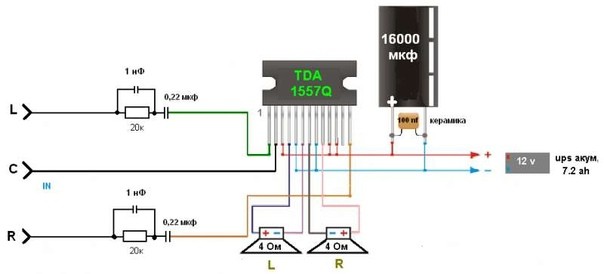
For variety, I’ll also attach another diagram from a subscriber whose TDA 1557Q amplifier has been working properly for more than 10 years in a row:
Amplifiers on Aliexpress
I also found kit kits on Ali on TDA. For example, this stereo amplifier is 15 watts per channel and costs $1. This power is quite enough to hang out in your room listening to your favorite tracks.

You can buy it.
And here it's ready right away

And in general, there are a lot of these amplifier modules on Aliexpress. Click on this link and choose any amplifier you like.
Circuit of a powerful five-channel low-frequency amplifier for a home audio center at minimal cost
In this article on the site Radio amateur, we will look at another simple amateur radio circuit - low frequency amplifier for home audio center.
Feature of this amplifier at low cost with sufficient high parameters. Amplifier built according to a combined circuit, in which there is one powerful low-frequency channel (40 W), reproducing frequencies up to 400 Hz, and a stereo amplifier, the channels of which are made according to a two-channel midrange (300-4000 Hz) - high-frequency (3000-30000 Hz) circuit with a power of 2x18 Tue Thus total output power amplifier is 106 W. For each channel, separate acoustic systems are used, made in separate housings. There are five acoustic systems in total: a low-frequency bottom and two each for mid and high frequencies.
The amplifier is made on the same type and inexpensive element base - TDA2030A (KR174UN19A) microcircuits and two transistors KT818GM and KT819GM. The amplifier is powered by a 200 W transformer.
The schematic diagram of the low-frequency channel is shown in Fig. 1:
Terminals X1, X2, X3 receive a stereo signal with a nominal level of 0.8 volts. The microcircuit is capable of developing power up to 18 W and to increase this value, the output of the microcircuit is enhanced by a push-pull cascade on transistors VT1, VT2, which begins to operate at a power of more than 15 W. The cascade circuit is distinguished by the fact that the collectors of the transistors are connected together, which allows the use of one common radiator for the output stage. The A1 chip requires a separate heatsink.
The amplifier board (Fig. No. 4) is made so that the microcircuit and transistors are located at opposite edges.
The circuit of the mid-high-frequency amplifier is shown in Figure No. 2:
 The diagram of only one stereo channel is shown, the second is exactly the same. The audio frequency of one of the stereo channels is supplied to terminals X1, X2. The mid-frequency amplifier is made on the A1 chip, and the high-frequency amplifier is made on the A2 chip. The microcircuits are installed on one common radiator. Therefore, on the printed circuit board (Fig. No. 5), the microcircuits are located at one edge.
 There are two such boards in the amplifier - one for each stereo channel. There are three jumpers on the board, made with mounting wire. One feeds the signal to the RF amplifier (it is advisable to make it with a shielded wire), and the other two supply power to the RF amplifier. The jumpers are located on the side of the printed conductors and are laid in the shortest direction.
The inter-board connections and power supply diagram are shown in Figure 3. The power supply is not stabilized; it is made of a power transformer, a bridge rectifier and a bank of smoothing capacitors.
 The stereo signal from the output of the preamplifier with a nominal level of 0.8 V is supplied to the XP1 connector. Directly next to the connector, trimming resistors R1-R5 are installed to set the ratio of the sound levels of stereo amplifiers and the low-frequency channel for a specific room. The transformer is made on the basis of the TS200 transformer from an old tube TV. All secondary windings were removed and two new ones were wound in their place - 50 turns of PEV 1.06 each. Connect the windings according to the diagram.
Radiators are made of U-shaped aluminum profile, which is used for suspended ceilings. For each radiator, two pieces approximately 15 cm long are cut. To increase the surface area over the entire surface, a hole is drilled through every centimeter and an M4 thread is cut. M4 screws 55 mm long are screwed into these holes, thus creating a needle-plate radiator (Fig. No. 6):
 The speaker systems use the most affordable dynamic loudspeakers with 4 ohm voice coils. Each acoustic system contains 4 speakers (Fig. No. 7). The low-frequency speaker contains 4 10GDSH-2 speakers, high-frequency speakers - four 4-GDV-1, mid-frequency speakers - 5GDSH-4.
 Acoustic systems are made of 20 mm thick chipboards, used in the manufacture of cabinet furniture. The dimensions of the workpieces shown in Figures No. 8, 9, 10 take into account exactly this chipboard thickness.

 The phase inverter pipe is made of 100 mm plastic gray sewer pipe 150 mm long. The pipe is glued into the hole with Moment-1 glue.